Structural Modeling
A structural turbine model in QBlade is defined by a set of ASCII input files that describe the overall dimensions of the turbine and the structural properties of the various turbine components. Structural properties in this sense relates broadly to the mass, inertia, stiffness and damping properties that are required by the structural simulation engine to resolve the structural dynamics. In most cases these structural properties need to be obtained from specialized software, for example software that is build to design a structural blade layout and can generate the cross-sectional mass, stiffness and damping properties that are required to setup a structural model in QBlade. An overview of the how the turbine structure is modeled through the integration of Project-CHRONO in QBlade can be found in the section: Multi Body Beam Formulation.
A structural model may be loaded into a turbine definition by loading the structural model main file through the open file dialog. When a structural model has been assigned to a turbine the structural model files may be examined by clicking View/Edit Struct. The dialog that shows the file contents can also be used to quickly change parameters of the structural model, without the need to modify and save the file outside of QBlade and then importing them again. This edit functionality however doesn’t cause to reload files from the file system, such that changing the string of a blade parameter table doesn’t lead to reloading the newly defined filename. Generally, it is recommended to only use this edit functionality to quickly change a few parameters, but to setup and work with the structural model files outside of QBlade in a text editor.
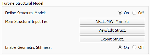
Fig. 100 The structural model dialog.
An overview of the file structure of the structural model definition files is shown in Fig. 101. The main input file needs to be loaded through the dialog. It contains the main turbine parameters and the location of the structural data tables for the definition of the tower and the blades.
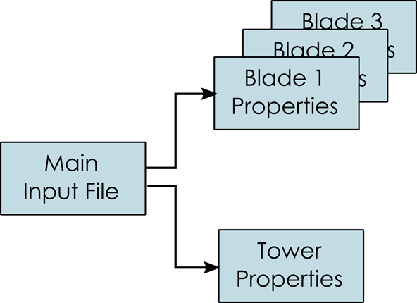
Fig. 101 The file structure of the structural model input files.
Geometric Stiffness and Aerodynamic Gradients
When a structural model is included, the user may activate the evaluation of geometric stiffness and aerodynamic gradients. These two options are intended for modal and stability analyses, where a consistent linearization of the structural and aerodynamic loading is required. Geometric stiffness accounts for stress-stiffening effects caused by the current load state, while aerodynamic gradients include the sensitivity of the aerodynamic forces to structural motion and deformation. For standard time-domain simulations, these options are typically not required and may be disabled to improve computational efficiency.
Main Structural Definition File
Within the main definition file the overall dimensions of the wind turbine are defined. Furthermore, nacelle mass and inertia and drivetrain properties are defined here. The main input file also contains the file locations of the structural data tables that define the detailed structural properties of the blades, tower and the torquetube (for a VAWT turbine). An overview of important parameters that define the turbine geometry and dimensions is shown in Fig. 102 and Fig. 106.
Exemplary Main File
An exemplary main structural input file for the NREL 5MW HAWT wind turbine is shown below and will be discussed in more detail in the following:
---------------------- QBLADE STRUCTURAL MODEL INPUT FILE -----------------
NREL 5MW Turbine
------------------------------- CHRONO PARAMETERS -------------------------
0.2             GLBGEOEPS - Global geometry epsilon for node placement

------------------------------- HAWT TURBINE CONFIGURATION ----------------
2.5             PRECONE - Rotor PreCone (deg) (HAWT only)
5               SHFTTILT - Turbine Shaft Tilt (deg) (HAWT only)
5.0191          OVERHANG - Rotor Overhang (m) (HAWT only)
1.96256         TWR2SHFT - Tower to Shaft distance (m) (HAWT only)

------------------------------- MASS AND INERTIA --------------------------
0.0             YAWBRMASS - Yaw Bearing Mass (kg) (HAWT only)
240000          NACMASS - Nacelle Mass (kg) (HAWT only)
1.9             NACCMX - Downwind distance from the tower-top to the nacelle CM (m) (HAWT only)
0.0             NACCMY - Lateral  distance from the tower-top to the nacelle CM (m) (HAWT only)
1.75            NACCMZ - Vertical distance from the tower-top to the nacelle CM (m) (HAWT only)
0 0 0 0 0 0     NACINER - Nacelle Inertia, up to 6 values xx,yy,zz,xy,xz,yz (HAWT only)
2607890         NACYINER - Nacelle Yaw Inertia, zz (kg*m^2), single value (HAWT only)
56780           HUBMASS - Hub Mass (kg)
0.0             HUBCM - Displacement of the Hub mass along the X_h axis (m) (HAWT only)
115926          HUBINER - Hub Inertia, up to 6 values xx,yy,zz,xy,xz,yz

------------------------------- NACELLE IMU -------------------------------
0.0             NACIMUX (m) (HAWT only)
0.0             NACIMUY (m) (HAWT only)
10.0            NACIMUZ (m) (HAWT only)

------------------------------- DRIVETRAIN MODEL --------------------------
97              GBRATIO - gearbox ratio (N)
1.0             GBOXEFF - gearbox efficiency (0-1)
1.0             GENEFF - generator efficiency  (0-1)
true            DRTRDOF - model drivetrain dynamics (true / false)
534.116         GENINER - Generator side (HSS) Inertia (kg*m^2)
867637000       DTTORSPR - Drivetrain torsional stiffness (N*m/rad)
6215000         DTTORDMP - Drivetrain torsional damping (N*m*s/rad)

------------------------------- BRAKE MODEL -------------------------------
0               BRKTORQUE - maximum brake torque
0               BRKDEPLOY - brake deploy time (s) (only used with DTU style controllers)
0               BRKDELAY - brake delay time (s) (only used with DTU style controllers)

------------------------------- SENSOR ERRORS -----------------------------
0               ERRORYAW - yaw error (deg) (HAWT only)
0               ERRORPITCH_1 - pitch error blade1 (deg)
0               ERRORPITCH_2 - pitch error blade2 (deg)
0               ERRORPITCH_3 - pitch error blade3 (deg)

------------------------------- BLADES ------------------------------------
3                               NUMBLD - Number of blades
NREL5MW_Blade.str               BLDFILE_1 - Name of file containing properties for blade 1
NREL5MW_Blade.str               BLDFILE_2 - Name of file containing properties for blade 2
NREL5MW_Blade.str               BLDFILE_3 - Name of file containing properties for blade 3

------------------------------- TOWER -------------------------------------
77.6                            TWRHEIGHT - Height of the tower (m)
OC3_Sparbuoy_Tower.str          TWRFILE - Name of file containing properties for the tower
OC3_Sparbuoy_Sub_LPMD.str       SUBFILE  - Name of the substructure file

------------------------------- DATA OUTPUT TYPES -------------------------
true                    FOR_OUT - store forces at all sensor locations
true                    DEF_OUT - store deflections at all sensor locations
true                    POS_OUT - store positions at all sensor locations
true                    VEL_OUT - store velocities at all sensor locations
true                    ACC_OUT - store accelerations at all sensor locations
true                    STR_OUT - store element strain at all sensor locations
true                    AER_OUT - store aerodynamic data at all sensor locations

------------------------------- DATA OUTPUT LOCATIONS ---------------------
any number, or zero, user defined positions can be chosen as output locations.
Locations can be assigned at any of the following components: blades, struts, tower
and guy cables. See the following examples for the used nomenclature:

BLD_1_1.0               - exemplary position, blade 1 at 100% normalized radius
BLD_1_0.8               - exemplary position, blade 1 at  80% normalized radius
BLD_1_0.5               - exemplary position, blade 1 at  50% normalized radius
BLD_1_0.4               - exemplary position, blade 1 at  40% normalized radius
BLD_1_0.2               - exemplary position, blade 1 at  20% normalized radius
BLD_1_0.0               - exemplary position, blade 1 at  00% normalized radius

BLD_2_1.0               - exemplary position, blade 2 at 100% normalized radius
BLD_2_0.8               - exemplary position, blade 2 at  80% normalized radius
BLD_2_0.5               - exemplary position, blade 2 at  50% normalized radius
BLD_2_0.4               - exemplary position, blade 2 at  40% normalized radius
BLD_2_0.2               - exemplary position, blade 2 at  20% normalized radius
BLD_2_0.0               - exemplary position, blade 2 at  00% normalized radius

BLD_3_1.0               - exemplary position, blade 3 at 100% normalized radius
BLD_3_0.8               - exemplary position, blade 3 at  80% normalized radius
BLD_3_0.5               - exemplary position, blade 3 at  50% normalized radius
BLD_3_0.4               - exemplary position, blade 3 at  40% normalized radius
BLD_3_0.2               - exemplary position, blade 3 at  20% normalized radius
BLD_3_0.0               - exemplary position, blade 3 at  00% normalized radius

TWR_1.00                - exemplary position, tower at 100% normalized height
TWR_0.90                - exemplary position, tower at  90% normalized height
TWR_0.80                - exemplary position, tower at  80% normalized height
TWR_0.70                - exemplary position, tower at  70% normalized height
TWR_0.60                - exemplary position, tower at  60% normalized height
TWR_0.50                - exemplary position, tower at  50% normalized height
TWR_0.40                - exemplary position, tower at  40% normalized height
TWR_0.30                - exemplary position, tower at  30% normalized height
TWR_0.20                - exemplary position, tower at  20% normalized height
TWR_0.10                - exemplary position, tower at  10% normalized height
TWR_0.00                - exemplary position, tower at   0% normalized height
The different sections of the structural model input file will now be briefly discussed.
HAWT Turbine Configuration
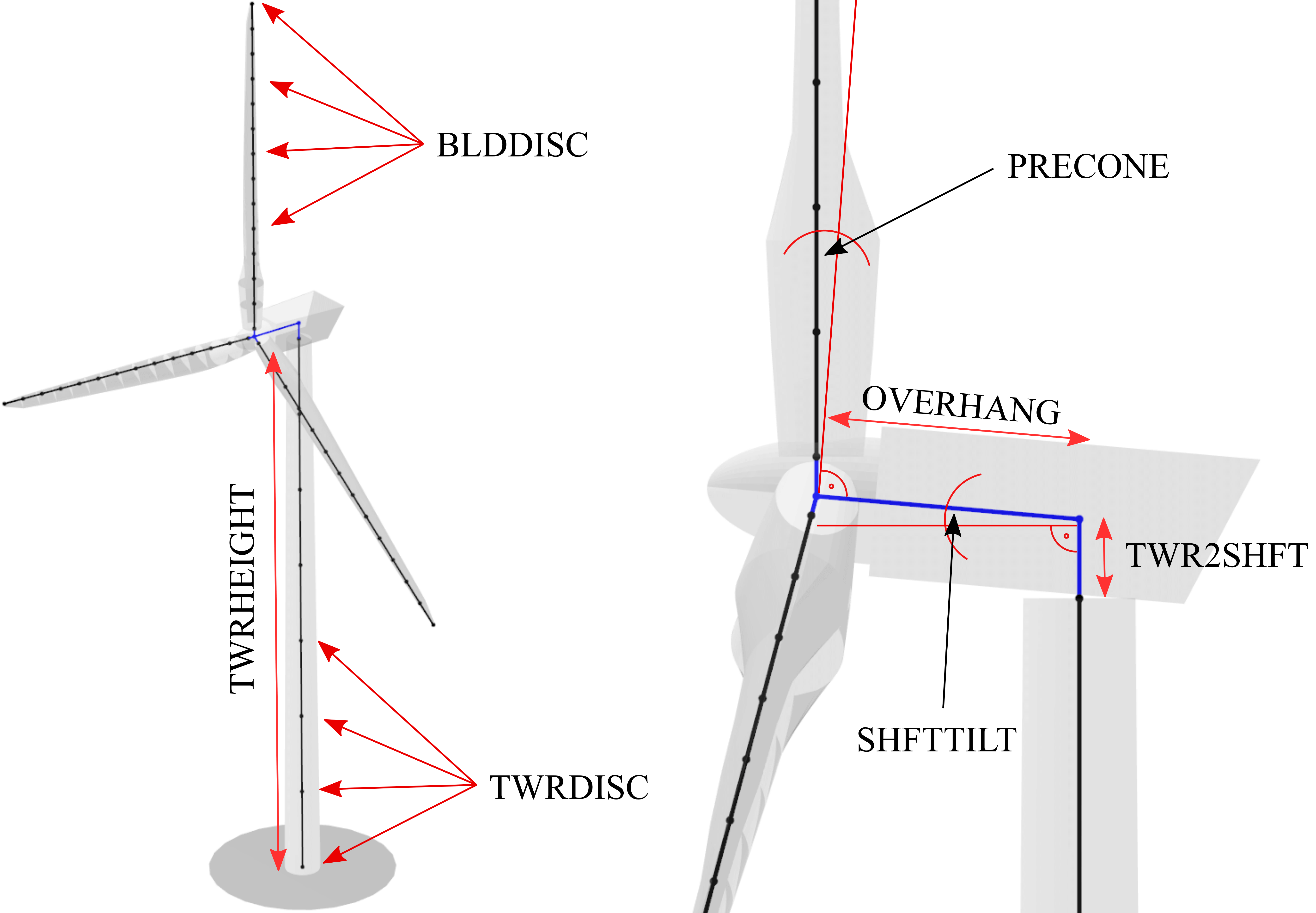
Fig. 102 Overview of geometrical parameters for a HAWT turbine.
------------------------------- HAWT TURBINE CONFIGURATION ----------------
2.5             PRECONE - Rotor PreCone (deg) (HAWT only)
5               SHFTTILT - Turbine Shaft Tilt (deg) (HAWT only)
5.0191          OVERHANG - Rotor Overhang (m) (HAWT only)
1.96256         TWR2SHFT - Tower to Shaft distance (m) (HAWT only)
In this section of the file the main geometrical turbine parameters are defined. These parameters are equivalent to the parameters discussed in Turbine Geometry.
Mass and Inertia Parameters
------------------------------- MASS AND INERTIA --------------------------
0.0             YAWBRMASS - Yaw Bearing Mass (kg) (HAWT only)
240000          NACMASS - Nacelle Mass (kg) (HAWT only)
1.9             NACCMX - Downwind distance from the tower-top to the nacelle CM (m) (HAWT only)
0.0             NACCMY - Lateral  distance from the tower-top to the nacelle CM (m) (HAWT only)
1.75            NACCMZ - Vertical distance from the tower-top to the nacelle CM (m) (HAWT only)
0 0 0 0 0 0     NACINER - Nacelle Inertia, up to 6 values xx,yy,zz,xy,xz,yz (HAWT only)
2607890         NACYINER - Nacelle Yaw Inertia, zz (kg*m^2), single value (HAWT only)
56780           HUBMASS - Hub Mass (kg)
0.0             HUBCM - Displacement of the Hub mass along the X_h axis (m) (HAWT only)
115926          HUBINER - Hub Inertia, up to 6 values xx,yy,zz,xy,xz,yz
In this section of the input file mass and inertia properties are assigned to the nacelle and the hub. It should be noted here that the parameter HUBINER should only account for the rotational inertia of the hub itself, and not account for the inertia of the rotor blades as this is explicity included through the finite element model.
Mass and Inertia Parameters Extended
NACCMthis (alternative) keyword can be used to set the center of mass of the nacelle in a single line by specifying the x, y and z positions before or after the keyword.
NACINERthis (alternative) keyword can be used to define the full inertia matrix of the nacelle (applied at the nacelle CM. Six values can be specified to define the XX, YY, ZZ, XY, XZ and YZ inertia of the nacelle.
HUBINERthis (alternative) keyword can be used to define the full inertia matrix of the hub (applied at the hub position. Six values can be specified to define the XX, YY, ZZ, XY, XZ and YZ inertia of the hub.
Nacelle Inertia Measurement Unit (IMU)
This section allows the user to specify the location of the nacelle-based Inertia Measurement Unit (IMU). The IMU location is defined in the Nacelle Coordinate System (see Local Sensor Coordinate Systems). At this specified location, acceleration data in the Nacelle Coordinate System is recorded.
NACIMUX: X_n position of the IMU (0 by default)
NACIMUY: X_n position of the IMU (0 by default)
NACIMUZ: X_n position of the IMU (0 by default)
The recorded IMU data can serve multiple purposes:
Populating a controller swap array (see Sending Turbine Data to a Wind Turbine Controller).
Supporting other custom analyses or applications.
Viewing in the Structural Time Graph during a simulation (see Live Results View).
The recorded acceleration data is stored under the following variable names:
X_n Nac. IMU Acc. [m^2/s]
Y_n Nac. IMU Acc. [m^2/s]
Z_n Nac. IMU Acc. [m^2/s]
Nacelle Drag Model
------------------------------- NACELLE DRAG ------------------------------
10.0            NACCAX - Downwind distance from the tower-top to the nacelle CD (m) (HAWT only)
0.0             NACCAY - Lateral  distance from the tower-top to the nacelle CD (m) (HAWT only)
1.75            NACCAZ - Vertical distance from the tower-top to the nacelle CD (m) (HAWT only)
15              NACARX - Downwind area of the nacelle (m^2) (HAWT only)
90              NACARY - Lateral  area of the nacelle (m^2) (HAWT only)
60              NACARZ - Vertical area of the nacelle (m^2) (HAWT only)
1.2             NACCDX - Downwind drag coefficient of the nacelle (-) (HAWT only)
1.2             NACCDY - Lateral drag coefficient of the nacelle (-) (HAWT only)
1.2             NACCDZ - Vertical drag coefficient of the nacelle (-) (HAWT only)
The nacelle drag model is optional. If no nacelle drag is defined no nacelle drag is applied. The nacelle drag can only be used with HAWT turbine definitions. The model defined a center of drag (NACCA) and three nacelle areas (NACAR) with three nacelle drag coefficients (NACCD). The total acting nacelle drag force in all directions is then summed up and applied at the center of drag (NACCD).
Drivetrain Parameters
------------------------------- DRIVETRAIN MODEL --------------------------
97              GBRATIO - gearbox ratio (N)
1.0             GBOXEFF - gearbox efficiency (0-1)
1.0             GENEFF - generator efficiency  (0-1)
true            DRTRDOF - model drivetrain dynamics (true / false)
534.116         GENINER - Generator side (HSS) Inertia (kg*m^2)
867637000       DTTORSPR - Drivetrain torsional stiffness (N*m/rad)
6215000         DTTORDMP - Drivetrain torsional damping (N*m*s/rad)
This section of the main input file defined the drive train model. The drive train model in QBlade is a simple 2 mass spring-damper model. An overview is given in Fig. 103. The parameter GBOXEFF define the mechanical losses within the gearbox, GENEFF defined the electrical losses within the generator.
Optionally, GENEFF and GBOXEFF can also define a table, instead of a scalar value for the efficiency:
GENEFF
RPM     EFF
4       0.8
9       0.9
12      0.98
The drivetrain is parameterized by the main shaft torsional stiffness and damping, a high speed side (HSS) generator inertia and the low speed side (LSS) inertia. The LSS inertia (of shaft and Hub combined) should be summed up and assigned to the HUBINER value.
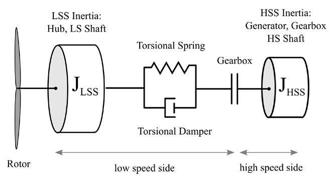
Fig. 103 An overview of the drivetrain model in QBlade.
Brake Model Parameters
------------------------------- BRAKE MODEL -------------------------------
0                       BRKTORQUE - maximum brake torque
0                       BRKDEPLOY - brake deploy time (s)
0                       BRKDELAY - brake delay time (s)
The brake in QBlade is defined as shown above. The brake is parameterized by a delay time, a deploy time, and a maximum brake torque. After the brake signal is emitted by the controller, or after a brake event is triggered, the brake is activated once the delay time (BRKDELAY) has elapsed. The brake torque is then ramped linearly to the maximum brake torque (BRKTORQUE) over the deploy time (BRKDEPLOY). The specified value of BRKTORQUE corresponds to the physical high-speed-shaft (HSS) brake torque. An overview of this process is shown in Fig. 104.
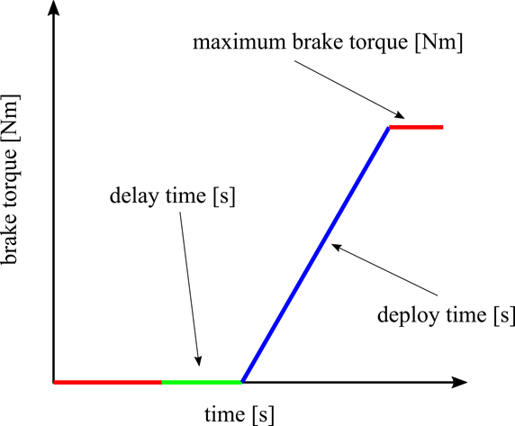
Fig. 104 An overview of the brake model in QBlade.
Modeling Sensor Errors
------------------------------- SENSOR ERRORS -----------------------------
0               ERRORYAW - yaw error (deg) (HAWT only)
0               ERRORPITCH_1 - pitch error blade1 (deg)
0               ERRORPITCH_2 - pitch error blade2 (deg)
0               ERRORPITCH_3 - pitch error blade3 (deg)
Sensor errors are defined for each blade pitch bearing sensor and the yaw bearing sensor. These errors are simply added to the corresponding signals as an offset.
Blade Parameters
------------------------------- BLADES ------------------------------------
3                               NUMBLD - Number of blades
NREL5MW_Blade.str               BLDFILE_1 - Name of file containing properties for blade 1
NREL5MW_Blade.str               BLDFILE_2 - Name of file containing properties for blade 2
NREL5MW_Blade.str               BLDFILE_3 - Name of file containing properties for blade 3
The location of the structural data tables for the blades is defined by the keywords shown above. The number of blades is defined by the parameter NUMBLD, this value overrides the number of blades that is defined in the turbine definition dialog. For each blade a keyword BLDFILE_X is searched for where the filename of the blade data table is defined. Different blade data tables can be assigned to each individual blade.
Custom Azimuthal Spacing
By default, the azimuthal spacing between rotor blades is given by \(\frac{360^\circ}{N}\), where \(N\) represents the number of blades. If a rotor is under construction and not all blades are attached, the azimuthal spacing can be customized to reflect the incomplete assembly, see Fig. 105.
------------------------------- BLADES ------------------------------------
120                             AZISPACING - Custom azimuthal spacing
2                               NUMBLD - Number of blades
NREL5MW_Blade.str               BLDFILE_1 - Name of file containing properties for blade 1
NREL5MW_Blade.str               BLDFILE_2 - Name of file containing properties for blade 2
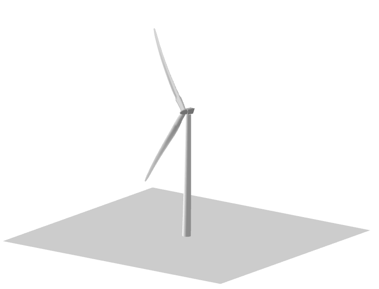
Fig. 105 An incomplete rotor with only 2 blades attached.
Tower Parameters
------------------------------- TOWER -------------------------------------
77.6                                            TWRHEIGHT - Height of the tower (m)
OC3_Sparbuoy_Tower.str          TWRFILE - Name of file containing properties for the tower
OC3_Sparbuoy_Sub_LPMD.str       SUBFILE  - Name of the substructure file
The structural tower data table is defined in a similar fashion as for the blades. The keyword TWRHEIGHT defines the absolute height of the tower. The keyword SUBFILE points to a substructure file that can be used to define a more complicated floating or bottom fixed substructure for offshore wind turbines or to model soil dynamics. If the keyword SUBFILE is not defined then the tower will simply be rigidly constrained to the ground. More information on how a substructure file is defined is found in the section: Substructure Modelling.
VAWT Specific Parameters
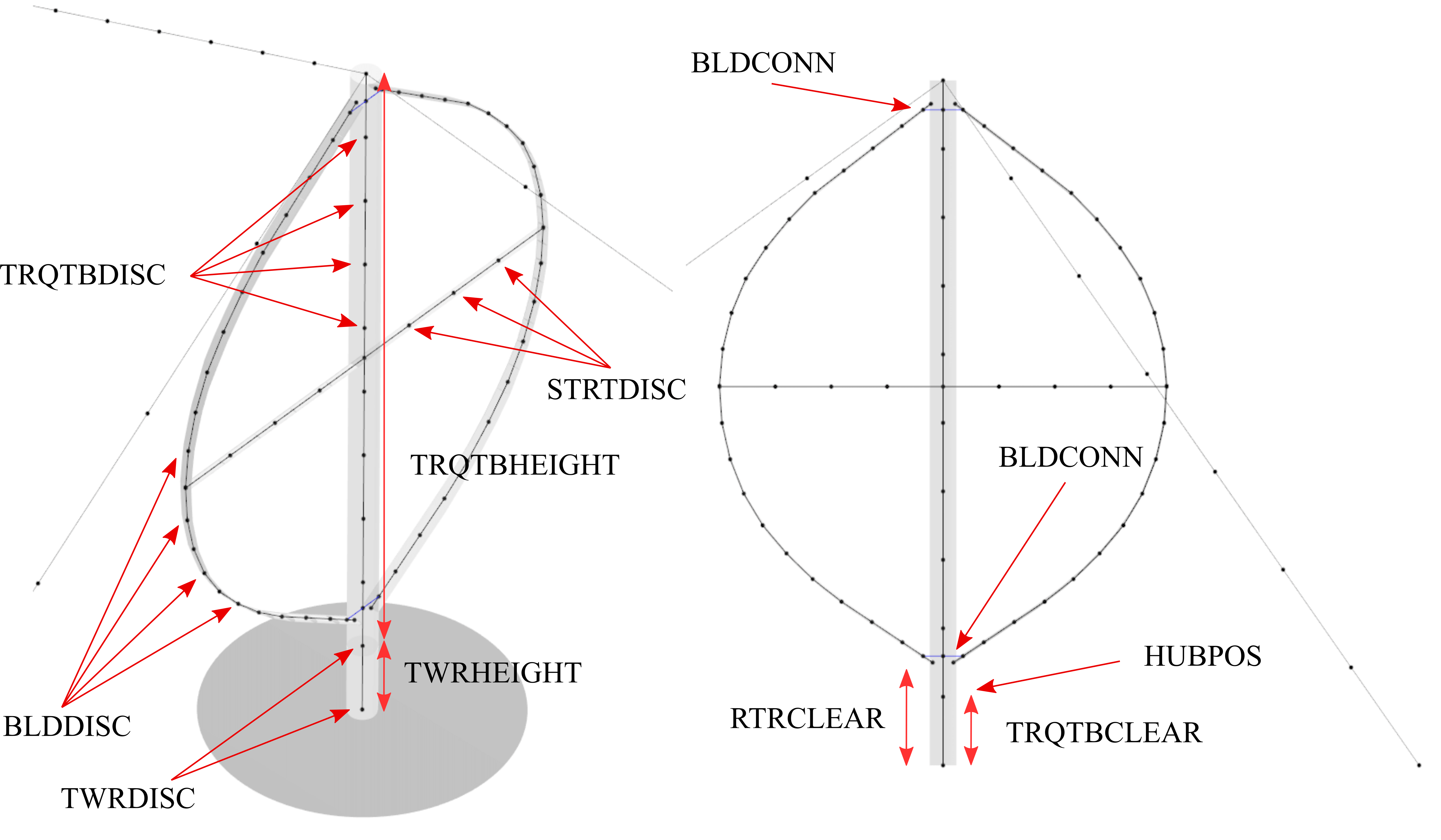
Fig. 106 Overview of geometrical parameters for a VAWT turbine.
Strut Parameters
------------------------------- STRUTS ------------------------------------
strutF100.dat           STRTFILE_1 - Name of file containing properties for strut1 (if blade has struts)
strutF100.dat           STRTFILE_2 - Name of file containing properties for strut2 (if blade has struts)
One structural properties table is defined for each strut. This table is used for the corresponding strut on each blade. So if there are three blades the parameter :code`STRTFILE_1` specifies the properties of strut 1 on each of the three blades.
Strut Constraint Table
In some cases, the user may want to specify a special constraint for the connection between the strut and the blade, or the strut and the torquetube, for example to model a hinge or similar. By default, each strut is connected rigidly to the blade and the torquetube. The STRUT_BLADE_CONSTRAINTS and STRUT_TORQUETUBE_CONSTRAINTS tables can be used to control the constrained degrees of freedom between struts, blades and the torquetube. By default, the DOFs are defined in the local coordinate system of the corresponding strut. Optionally, by adding an additional 9th column to the table and setting its value to 1, the local coordinate system of the blade or torquetube is used to setup the constraint DOFs.
STRUT_BLADE_CONSTRAINTS
STR_ID  BLD_ID  DoF_X   DoF_Y   DoF_Z   DoF_rX  DoF_rY  DoF_rZ
1       1       1       1       1       1       0       1
1       2       1       1       1       1       0       1
This exemplary table models a hinge connection between strut 1 and blade 1 and strut 1 and blade 2, where the rotational degree of freedom around the local y-axis of the strut is not constrained.
STRUT_TORQUETUBE_CONSTRAINTS
STR_ID  BLD_ID  DoF_X   DoF_Y   DoF_Z   DoF_rX  DoF_rY  DoF_rZ
1       1       1       1       1       1       0       1
1       2       1       1       1       1       0       1
This exemplary table models a hinge connection between strut 1 and the torquetube and strut 1 and the torquetube, where the rotational degree of freedom around the local y-axis of the strut is not constrained.
Tower and Torquetube Parameters
------------------------------- TOWER AND TORQUE TUBE ---------------------
20.845                  TWRHEIGHT -  Height of the (fixed - non rotating) tower [m]
tower.dat               TWRFILE - Name of file containing properties for the tower

2.4376                  TRQTBHEIGHT - Height (or length) of the torque tube (the rotating part of the tower) [m]
torquetube.dat          TRQTBFILE - Name of file containing properties for the torque tube

18.427                  TRQTBCLEAR - Clearance of the torque tube, must be <= TWRHEIGHT [m]
18.427                  HUBPOS - Height of the generator hub that is connecting the torque tube with the fixed tower (VAWT only) [m]
2.4376                  TRQTBCONN - Absolute height position, starting after torque tube clearance, of a frictionless bearing that connects the torque tube to the fixed tower [m]

0.5                     BLDCONN - Absolute height position, starting after rotor clearance, of blade of the rigid blade torque tube connection 1 in [m] (VAWT only)
40.853                  BLDCONN - Absolute height position, starting after rotor clearance, of blade of the rigid blade torque tube connection 2 in [m] (VAWT only)

15.635                  RTRCLEAR - Rotor clearance
See Fig. 106 for a visual explanation of each parameter.
Cable Parameters
------------------------------- BLDDE CABLES (VAWT only) ------------------
cable.dat               CABFILE - file containing the definitions of cables
An exemplary cable definition file is shown here: Cable Structural Data File.
Gravity Direction
The direction of the gravitational force can be customized by optionally specifying a gravity direction vector using the GRAVITY_DIR table in the main structural input file. QBlade will automatically normalize the vector upon reading the input to ensure it represents only the direction and not the magnitude of gravity. The default direction is (0,0,-1).
GRAVITY_DIR
X       Y       Z
0       0       -1
Loading Data and Sensor Locations
------------------------------- DATA OUTPUT TYPES -------------------------
true                    FOR_OUT - store forces at all sensor locations
true                    DEF_OUT - store deflections at all sensor locations
true                    POS_OUT - store positions at all sensor locations
true                    VEL_OUT - store velocities at all sensor locations
true                    ACC_OUT - store accelerations at all sensor locations
true                    STR_OUT - store element strain at all sensor locations
true                    AER_OUT - store aerodynamic data at all sensor locations

------------------------------- SENSOR OUTPUT LOCATIONS -------------------
any number, or zero, user defined positions can be chosen as output locations.
Locations can be assigned at any of the following components: blades, struts, tower
and guy cables. See the following examples for the used nomenclature:

BLD_1_1.0               - exemplary position, blade 1 at 100% normalized radius
BLD_1_0.8               - exemplary position, blade 1 at  80% normalized radius
BLD_1_0.5               - exemplary position, blade 1 at  50% normalized radius
BLD_1_0.4               - exemplary position, blade 1 at  40% normalized radius
BLD_1_0.2               - exemplary position, blade 1 at  20% normalized radius
BLD_1_0.0               - exemplary position, blade 1 at  00% normalized radius

BLD_2_1.0               - exemplary position, blade 2 at 100% normalized radius
BLD_2_0.8               - exemplary position, blade 2 at  80% normalized radius
BLD_2_0.5               - exemplary position, blade 2 at  50% normalized radius
BLD_2_0.4               - exemplary position, blade 2 at  40% normalized radius
BLD_2_0.2               - exemplary position, blade 2 at  20% normalized radius
BLD_2_0.0               - exemplary position, blade 2 at  00% normalized radius

BLD_3_1.0               - exemplary position, blade 3 at 100% normalized radius
BLD_3_0.8               - exemplary position, blade 3 at  80% normalized radius
BLD_3_0.5               - exemplary position, blade 3 at  50% normalized radius
BLD_3_0.4               - exemplary position, blade 3 at  40% normalized radius
BLD_3_0.2               - exemplary position, blade 3 at  20% normalized radius
BLD_3_0.0               - exemplary position, blade 3 at  00% normalized radius

TWR_1.00                - exemplary position, tower at 100% normalized height
TWR_0.90                - exemplary position, tower at  90% normalized height
TWR_0.80                - exemplary position, tower at  80% normalized height
TWR_0.70                - exemplary position, tower at  70% normalized height
TWR_0.60                - exemplary position, tower at  60% normalized height
TWR_0.50                - exemplary position, tower at  50% normalized height
TWR_0.40                - exemplary position, tower at  40% normalized height
TWR_0.30                - exemplary position, tower at  30% normalized height
TWR_0.20                - exemplary position, tower at  20% normalized height
TWR_0.10                - exemplary position, tower at  10% normalized height
TWR_0.00                - exemplary position, tower at   0% normalized height
The last part of the main structural input file deals with the definition of loading data and sensor locations. The locations at which the data will be stored are defined through the following keywords that can be placed anywhere in the structural model main input file:
BLD_X_Y: Stores data for blade X at the normalized curved length position YSTR_X_Y_Z: Stores data for strut Y of blade X at the normalized curved length position ZTWR_X: Stores data for the tower at the normalized curved length position XTRQ_X: Stores data for the torque tube at the normalized curved length position XCAB_X_Y: Stores data for guy cable X at the normalized curved length position Y
Auto-generated Variable Names
Furthermore data is automatically stored at each inter body connection of the model. Each inter body connection is identified by a combination of two body name tags and a z value that gives the height position at which the connection was created during the model definition. In the following two exemplary auto-generated variable names are shown and explained:
- Y l Mom. TRQ - BLD_3 z=29.7m
The moment around the local Y axis at the connection between the torque tube and blade 3, which was defined at a height of 29.7m. This result is given in the local coordinates of the torque tube since the TRQ tag is the first tag in the variable name.
- X l For. STR_2_2 - BLD_2 z=27.5m
This example defines the local reaction force at the connection between the top strut of blade 2 and blade 2, given for the local X axis of the strut.
Data Types
Seven different data types can be specified to be stored (true) or not (false) at all locations that are specified or automatically generated. It is recommended to only activate the sensor output that are required for the particular analysis to reduce the overall memory requirements and size of project and data files generated by QBlade. The different types of data that can be stored for each sensor are:
true FOR_OUT - store forces at all sensor locations true DEF_OUT - store deflections at all sensor locations true POS_OUT - store positions at all sensor locations true VEL_OUT - store velocities at all sensor locations true ACC_OUT - store accelerations at all sensor locations true STR_OUT - store element strain at all sensor locations true AER_OUT - store aerodynamic data at all sensor locations
The forces and moments from a structural body are internal shear forces and bending moments, while those at inter-body connections are reaction forces and moments. See Local Body Coordinate Systems for more on coordinate system conventions.
Structural Definition of Bodies
For an aeroelastic wind turbine setup, each body in the multi-body setup is defined by its own structural data table. These datatables contain the crosssectional, structural information that is required to setup the beam elements, which make up a structural body. The structural bodies that can be defined with structural datatables are: blades, struts, tower, torquetube, cable elements and the substructure. Different types of elements can be used to setup these structural bodies. The different element types are briefly explained below:
Euler-Bernoulli Beam
Euler-Bernoulli beams are the most basic type of beams in QBlade. These beams rely on the thin beam theory and thus do not consider shear forces. They are been implemented using a corotational approach, which enables the handling of large deflections and displacements.
Timoshenko Beam
Timoshenko beams represent a more advanced beam model in QBlade compared to Euler-Bernoulli beams. These beams incorporate the effects of shear deformation, making them suitable for a wider range of bodies. Similar to Euler-Bernoulli beams, Timoshenko beams are implemented with a corotational formulation to accommodate large displacements and deflections while providing a more accurate representation of the beam’s behavior.
Timoshenko Beam FPM
Timoshenko beams with a Fully Populated Stiffness Matrix (FPM) represent the most sophisticated and versatile beam model in QBlade. Timoshenko FPM beams take into account also off-diagonal coupling effects, such as bend-twist coupling, which is particularly important for an accurate modeling of very large blades. The Timoshenko FPM element is reserved to be used excludively to model rotor blades or struts.
ANCF Cable Element
The ANCF Cable element in QBlade is used for an efficient simulation of slender, cable like structures such as mooring lines and blade cables. These elements utilize Absolute Nodal Coordinate Formulation to obtain accurate and efficient results for complex mooring system configurations or tower guywires (see Cable Structural Data File and Mooring Elements).
Blade, Strut and Tower Structural Data Files
The cross-sectional beam properties of the blade, tower and strut bodies have to be defined in the form of structural data tables. The definition of the table entries are found in Blade and Strut Euler Bernoulli and Timoshenko Datatable, Blade and Strut Timoshenko FPM Datatable and Tower and Torquetube Euler Bernoulli and Timoshenko Datatable. An exemplary structural blade data table for a Timoshenko Beam is shown below:
0.0024  RAYLEIGHDMP

1.0             STIFFTUNER
1.0             MASSTUNER

0               INTPTYPE 0-LINEAR; 1-AKIMA; 2-HERMITE; 3-C2SPLINE
1               BEAMTYPE 0-EULER; 1-TIMOSHENKO; 2-TIMOSHENKO_FPM
1               DISCTYPE 0-LINEAR; 1-COSINE; 2-STRUCT; 3-AERO
60              DISC

ADDMASS_0.50 0.00 - add a point mass at relative position 0.50 with 0.00kg mass

LENFRACT_[-]  MASSD_[kg/m]  EIx_[N.m^2]   EIy_[N.m^2]   EA_[N]        GJ_[N.m^2]    GA_[N]        STRPIT_[deg]  KSX_[-]       KSY_[-]       RGX_[-]       RGY_[-]       XCM_[-]       YCM_[-]       XCE_[-]       YCE_[-]       XCS_[-]       YCS_[-]
0.0000E+00    7.1502E+02    1.8116E+10    1.8116E+10    9.7300E+09    5.5600E+09    6.9500E+08    0.0000E+00    5.0000E-01    5.0000E-01    3.2931E-01    3.2936E-01    -4.7995E-05   0.0000E+00    0.0000E+00    0.0000E+00    0.0000E+00    0.0000E+00
3.2520E-03    7.1502E+02    1.8116E+10    1.8116E+10    9.7300E+09    5.5600E+09    6.9500E+08    0.0000E+00    5.0000E-01    5.0000E-01    3.2931E-01    3.2936E-01    -4.7995E-05   0.0000E+00    0.0000E+00    0.0000E+00    0.0000E+00    0.0000E+00
1.9512E-02    8.1446E+02    1.9418E+10    1.9558E+10    1.0790E+10    5.4300E+09    7.7070E+08    0.0000E+00    5.0000E-01    5.0000E-01    3.2685E-01    3.2307E-01    7.0102E-03    0.0000E+00    0.0000E+00    0.0000E+00    0.0000E+00    0.0000E+00
3.5772E-02    7.7991E+02    1.7458E+10    1.9502E+10    1.0067E+10    4.9900E+09    7.1910E+08    0.0000E+00    5.0000E-01    5.0000E-01    3.0601E-01    3.1861E-01    3.8932E-03    0.0000E+00    5.4989E-03    0.0000E+00    5.4989E-03    0.0000E+00
5.2033E-02    7.7937E+02    1.5288E+10    1.9782E+10    9.8672E+09    4.6700E+09    7.0480E+08    0.0000E+00    5.0000E-01    5.0000E-01    2.8228E-01    3.1667E-01    5.4728E-03    0.0000E+00    1.5995E-02    0.0000E+00    1.5995E-02    0.0000E+00
6.8293E-02    6.2399E+02    1.0783E+10    1.4854E+10    7.6076E+09    3.4700E+09    5.4340E+08    0.0000E+00    5.0000E-01    5.0000E-01    2.6375E-01    3.0599E-01    1.4164E-02    0.0000E+00    2.8457E-02    0.0000E+00    2.8457E-02    0.0000E+00
8.4553E-02    4.7421E+02    7.2296E+09    1.0220E+10    5.4908E+09    2.3200E+09    3.9220E+08    0.0000E+00    5.0000E-01    5.0000E-01    2.4658E-01    2.9224E-01    2.5352E-02    0.0000E+00    4.0201E-02    0.0000E+00    4.0201E-02    0.0000E+00
1.0081E-01    4.4659E+02    6.3098E+09    9.1448E+09    4.9714E+09    1.9100E+09    3.5510E+08    0.0000E+00    5.0000E-01    5.0000E-01    2.3129E-01    2.8160E-01    3.5071E-02    0.0000E+00    5.1288E-02    0.0000E+00    5.1288E-02    0.0000E+00
1.1707E-01    4.2193E+02    5.5286E+09    8.0626E+09    4.4940E+09    1.5700E+09    3.2100E+08    0.0000E+00    5.0000E-01    5.0000E-01    2.1690E-01    2.7057E-01    4.6278E-02    0.0000E+00    6.4150E-02    0.0000E+00    6.4150E-02    0.0000E+00
1.3333E-01    4.0237E+02    4.9798E+09    6.8838E+09    4.0348E+09    1.1600E+09    2.8820E+08    0.0000E+00    5.0000E-01    5.0000E-01    2.0504E-01    2.5549E-01    5.5352E-02    0.0000E+00    7.6335E-02    0.0000E+00    7.6335E-02    0.0000E+00
1.4959E-01    4.2090E+02    4.9364E+09    7.0098E+09    4.0376E+09    1.0000E+09    2.8840E+08    0.0000E+00    5.0000E-01    5.0000E-01    1.9141E-01    2.4658E-01    6.7216E-02    0.0000E+00    8.7894E-02    0.0000E+00    8.7894E-02    0.0000E+00
1.6585E-01    4.4898E+02    4.6914E+09    7.1680E+09    4.1692E+09    8.5600E+08    2.9780E+08    0.0000E+00    5.0000E-01    5.0000E-01    1.7635E-01    2.4202E-01    6.8242E-02    0.0000E+00    1.0107E-01    0.0000E+00    1.0107E-01    0.0000E+00
1.8211E-01    4.3897E+02    3.9494E+09    7.2716E+09    4.0824E+09    6.7200E+08    2.9160E+08    0.0000E+00    5.0000E-01    5.0000E-01    1.6368E-01    2.4883E-01    6.6958E-02    0.0000E+00    1.1356E-01    0.0000E+00    1.1356E-01    0.0000E+00
1.9837E-01    4.2777E+02    3.3866E+09    7.0812E+09    4.0866E+09    5.4700E+08    2.9190E+08    0.0000E+00    5.0000E-01    5.0000E-01    1.5436E-01    2.5762E-01    5.8711E-02    0.0000E+00    1.2168E-01    0.0000E+00    1.2168E-01    0.0000E+00
2.1463E-01    4.0169E+02    2.9344E+09    6.2440E+09    3.6680E+09    4.4900E+08    2.6200E+08    0.0000E+00    5.0000E-01    5.0000E-01    1.4756E-01    2.5220E-01    5.9779E-02    0.0000E+00    1.2323E-01    0.0000E+00    1.2323E-01    0.0000E+00
2.3089E-01    3.7157E+02    2.5690E+09    5.0484E+09    3.1472E+09    3.3600E+08    2.2480E+08    0.0000E+00    5.0000E-01    5.0000E-01    1.4153E-01    2.4160E-01    6.8041E-02    0.0000E+00    1.2262E-01    0.0000E+00    1.2262E-01    0.0000E+00
2.4715E-01    3.6805E+02    2.3884E+09    4.9490E+09    3.0114E+09    3.1100E+08    2.1510E+08    0.0000E+00    5.0000E-01    5.0000E-01    1.3776E-01    2.4075E-01    6.9442E-02    0.0000E+00    1.2360E-01    0.0000E+00    1.2360E-01    0.0000E+00
2.6341E-01    3.6496E+02    2.2722E+09    4.8076E+09    2.8826E+09    2.9200E+08    2.0590E+08    0.0000E+00    5.0000E-01    5.0000E-01    1.3583E-01    2.3952E-01    7.0957E-02    0.0000E+00    1.2269E-01    0.0000E+00    1.2269E-01    0.0000E+00
2.9593E-01    3.5737E+02    2.0496E+09    4.5010E+09    2.6138E+09    2.6100E+08    1.8670E+08    0.0000E+00    5.0000E-01    5.0000E-01    1.3211E-01    2.3616E-01    7.3227E-02    0.0000E+00    1.2305E-01    0.0000E+00    1.2305E-01    0.0000E+00
3.2846E-01    3.4754E+02    1.8284E+09    4.2434E+09    2.3576E+09    2.2900E+08    1.6840E+08    0.0000E+00    5.0000E-01    5.0000E-01    1.2843E-01    2.3363E-01    7.8424E-02    0.0000E+00    1.2360E-01    0.0000E+00    1.2360E-01    0.0000E+00
3.6098E-01    3.3910E+02    1.5890E+09    3.9956E+09    2.1462E+09    2.0100E+08    1.5330E+08    0.0000E+00    5.0000E-01    5.0000E-01    1.2363E-01    2.3296E-01    7.8316E-02    0.0000E+00    1.2421E-01    0.0000E+00    1.2421E-01    0.0000E+00
3.9350E-01    3.3050E+02    1.3619E+09    3.7506E+09    1.9446E+09    1.7400E+08    1.3890E+08    0.0000E+00    5.0000E-01    5.0000E-01    1.1868E-01    2.3275E-01    7.8557E-02    0.0000E+00    1.2284E-01    0.0000E+00    1.2284E-01    0.0000E+00
4.2602E-01    3.1040E+02    1.1024E+09    3.4468E+09    1.6324E+09    1.4400E+08    1.1660E+08    0.0000E+00    5.0000E-01    5.0000E-01    1.1139E-01    2.2858E-01    8.7855E-02    0.0000E+00    1.2396E-01    0.0000E+00    1.2396E-01    0.0000E+00
4.5854E-01    3.0238E+02    8.7584E+08    3.1388E+09    1.4322E+09    1.2000E+08    1.0230E+08    0.0000E+00    5.0000E-01    5.0000E-01    1.0343E-01    2.2650E-01    8.5572E-02    0.0000E+00    1.2279E-01    0.0000E+00    1.2279E-01    0.0000E+00
4.9106E-01    2.7734E+02    6.8124E+08    2.7342E+09    1.1687E+09    8.1200E+07    8.3480E+07    0.0000E+00    5.0000E-01    5.0000E-01    9.6993E-02    2.2246E-01    8.9951E-02    0.0000E+00    1.2425E-01    0.0000E+00    1.2425E-01    0.0000E+00
5.2358E-01    2.6666E+02    5.3466E+08    2.5550E+09    1.0475E+09    6.9100E+07    7.4820E+07    0.0000E+00    5.0000E-01    5.0000E-01    9.0303E-02    2.2464E-01    8.8604E-02    0.0000E+00    1.2292E-01    0.0000E+00    1.2292E-01    0.0000E+00
5.5610E-01    2.5451E+02    4.0894E+08    2.3338E+09    9.2302E+08    5.7500E+07    6.5930E+07    0.0000E+00    5.0000E-01    5.0000E-01    8.3338E-02    2.2561E-01    8.5360E-02    0.0000E+00    1.2426E-01    0.0000E+00    1.2426E-01    0.0000E+00
5.8862E-01    2.3236E+02    3.1458E+08    1.8284E+09    7.6076E+08    4.5900E+07    5.4340E+07    0.0000E+00    5.0000E-01    5.0000E-01    7.9830E-02    2.2268E-01    8.4224E-02    0.0000E+00    1.2569E-01    0.0000E+00    1.2569E-01    0.0000E+00
6.2114E-01    2.1094E+02    2.3870E+08    1.5848E+09    6.4806E+08    3.6000E+07    4.6290E+07    0.0000E+00    5.0000E-01    5.0000E-01    7.6068E-02    2.2493E-01    7.9155E-02    0.0000E+00    1.2420E-01    0.0000E+00    1.2420E-01    0.0000E+00
6.5366E-01    1.8894E+02    1.7584E+08    1.3234E+09    5.3970E+08    2.7400E+07    3.8550E+07    0.0000E+00    5.0000E-01    5.0000E-01    7.2179E-02    2.2638E-01    7.0245E-02    0.0000E+00    1.2575E-01    0.0000E+00    1.2575E-01    0.0000E+00
6.8618E-01    1.7387E+02    1.2601E+08    1.1837E+09    5.3116E+08    2.0900E+07    3.7940E+07    0.0000E+00    5.0000E-01    5.0000E-01    6.6939E-02    2.4642E-01    4.3584E-02    0.0000E+00    1.2414E-01    0.0000E+00    1.2414E-01    0.0000E+00
7.1870E-01    1.6262E+02    1.0725E+08    1.0202E+09    4.6004E+08    1.8500E+07    3.2860E+07    0.0000E+00    5.0000E-01    5.0000E-01    6.6508E-02    2.4696E-01    3.6522E-02    0.0000E+00    1.2581E-01    0.0000E+00    1.2581E-01    0.0000E+00
7.5122E-01    1.4632E+02    9.0874E+07    7.9786E+08    3.7576E+08    1.6300E+07    2.6840E+07    0.0000E+00    5.0000E-01    5.0000E-01    6.6749E-02    2.4513E-01    4.5051E-02    0.0000E+00    1.2407E-01    0.0000E+00    1.2407E-01    0.0000E+00
7.8374E-01    1.3644E+02    7.6314E+07    7.0966E+08    3.2886E+08    1.4500E+07    2.3490E+07    0.0000E+00    5.0000E-01    5.0000E-01    6.6198E-02    2.4839E-01    4.0603E-02    0.0000E+00    1.2588E-01    0.0000E+00    1.2588E-01    0.0000E+00
8.1626E-01    1.1296E+02    6.1054E+07    5.1814E+08    2.4402E+08    9.0700E+06    1.7430E+07    0.0000E+00    5.0000E-01    5.0000E-01    6.6835E-02    2.4572E-01    4.5184E-02    0.0000E+00    1.2398E-01    0.0000E+00    1.2398E-01    0.0000E+00
8.4878E-01    1.0403E+02    4.9476E+07    4.5486E+08    2.1154E+08    8.0600E+06    1.5110E+07    0.0000E+00    5.0000E-01    5.0000E-01    6.6071E-02    2.5059E-01    3.7078E-02    0.0000E+00    1.2596E-01    0.0000E+00    1.2596E-01    0.0000E+00
8.8130E-01    9.5044E+01    3.9354E+07    3.9508E+08    1.8158E+08    7.0800E+06    1.2970E+07    0.0000E+00    5.0000E-01    5.0000E-01    6.5143E-02    2.5583E-01    2.7860E-02    0.0000E+00    1.2388E-01    0.0000E+00    1.2388E-01    0.0000E+00
8.9756E-01    8.7412E+01    3.4664E+07    3.5378E+08    1.6030E+08    6.0900E+06    1.1450E+07    0.0000E+00    5.0000E-01    5.0000E-01    6.5499E-02    2.5874E-01    2.3511E-02    0.0000E+00    1.2342E-01    0.0000E+00    1.2342E-01    0.0000E+00
9.1382E-01    7.6781E+01    3.0408E+07    3.0478E+08    1.0923E+08    5.7500E+06    7.8020E+06    0.0000E+00    5.0000E-01    5.0000E-01    6.7897E-02    2.3439E-01    5.8270E-02    0.0000E+00    1.2811E-01    0.0000E+00    1.2811E-01    0.0000E+00
9.3008E-01    7.2427E+01    2.6516E+07    2.8140E+08    1.0009E+08    5.3300E+06    7.1490E+06    0.0000E+00    5.0000E-01    5.0000E-01    6.8201E-02    2.4056E-01    5.2444E-02    0.0000E+00    1.2366E-01    0.0000E+00    1.2366E-01    0.0000E+00
9.3821E-01    6.9786E+01    2.3842E+07    2.6166E+08    9.2246E+07    4.9400E+06    6.5890E+06    0.0000E+00    5.0000E-01    5.0000E-01    6.8860E-02    2.4603E-01    5.0497E-02    0.0000E+00    1.2917E-01    0.0000E+00    1.2917E-01    0.0000E+00
9.4634E-01    6.2494E+01    1.9628E+07    1.5876E+08    6.3224E+07    4.2400E+06    4.5160E+06    0.0000E+00    5.0000E-01    5.0000E-01    7.0184E-02    2.2737E-01    7.8974E-02    0.0000E+00    1.2693E-01    0.0000E+00    1.2693E-01    0.0000E+00
9.5447E-01    5.8886E+01    1.6002E+07    1.3789E+08    5.3326E+07    3.6600E+06    3.8090E+06    0.0000E+00    5.0000E-01    5.0000E-01    6.9485E-02    2.3028E-01    7.8893E-02    0.0000E+00    1.3004E-01    0.0000E+00    1.3004E-01    0.0000E+00
9.6260E-01    5.5273E+01    1.2830E+07    1.1879E+08    4.4534E+07    3.1300E+06    3.1810E+06    0.0000E+00    5.0000E-01    5.0000E-01    6.8804E-02    2.3374E-01    7.7403E-02    0.0000E+00    1.2753E-01    0.0000E+00    1.2753E-01    0.0000E+00
9.7073E-01    5.1724E+01    1.0080E+07    1.0163E+08    3.6904E+07    2.6400E+06    2.6360E+06    0.0000E+00    5.0000E-01    5.0000E-01    6.8277E-02    2.3815E-01    7.4901E-02    0.0000E+00    1.2462E-01    0.0000E+00    1.2462E-01    0.0000E+00
9.7886E-01    4.8253E+01    7.5502E+06    8.5064E+07    2.9918E+07    2.1700E+06    2.1370E+06    0.0000E+00    5.0000E-01    5.0000E-01    6.6807E-02    2.4331E-01    7.4254E-02    0.0000E+00    1.2173E-01    0.0000E+00    1.2173E-01    0.0000E+00
9.8699E-01    4.3884E+01    4.6004E+06    6.4260E+07    2.1308E+07    1.5800E+06    1.5220E+06    0.0000E+00    5.0000E-01    5.0000E-01    6.1430E-02    2.4597E-01    8.1096E-02    0.0000E+00    1.2205E-01    0.0000E+00    1.2205E-01    0.0000E+00
9.9512E-01    1.2062E+01    2.5004E+05    6.6094E+06    4.8496E+06    2.5000E+05    3.4640E+05    0.0000E+00    5.0000E-01    5.0000E-01    5.4262E-02    2.6302E-01    7.4337E-02    0.0000E+00    1.2247E-01    0.0000E+00    1.2247E-01    0.0000E+00
1.0000E+00    1.0867E+01    1.6996E+05    5.0106E+06    3.5294E+06    1.9000E+05    2.5210E+05    0.0000E+00    5.0000E-01    5.0000E-01    4.4641E-02    2.6025E-01    7.1103E-02    0.0000E+00    1.2487E-01    0.0000E+00    1.2487E-01    0.0000E+00


RGBCOLOR
R       G       B
220     220     220
The keyword RAYLEIGHDMP: defines a stiffness proportional Rayleigh damping coefficient (see Damping of Structural Bodies). The parameters STIFFTUNER and MASSTUNER can be used to tune the global stiffness or mass properties of the data table through a multiplication by this factor. The keyword RGBCOLOR defines the rgb values that are used to color the structural body during the 3D visualization.
The keyword INTPTYPE controls the interpolation of the cross-sectional quantities between the user specified data table and the structural elements. Options are: 0-LINEAR; 1-AKIMA; 2-HERMITE; 3-C2SPLINE
The keyword BEAMTYPE sets the type of structural beam, based on which the structural datatable is interpreted. Options are: 0-EULER; 1-TIMOSHENKO; 2-TIMOSHENKO_FPM. Please note that the user defined datatable has to match the selected beam type (see Blade and Strut Euler Bernoulli and Timoshenko Datatable and Blade and Strut Timoshenko FPM Datatable)
The keyword DISCTYPE controls the discretization type of the structural body. Options are: 0-LINEAR; 1-COSINE; 2-STRUCT; 3-AERO. LINEAR is the standard linear discretization, based over the number of nodes specified by the keyword <num> DISC. COSINE is a cosine distribution based on the number of nodes specified by the keyword <num> DISC. STRUCT discretizes the structural body based on the structural data table. AERO discretizes the structural body based on the discretization of the aerodynamic blade design.
The keyword <num> DISC controls the number of structural nodes that are distributed over the length of the body:
The keyword ADDMASS_<pos> can be used to add a mass at the normalized position <pos>. ADDMASS_<pos> can be followed by up to 7 numeric values (at least one) to assign mass and rotational inertia properties. For example: ADDMASS_0.2 10 1 2 3 4 5 6 adds a mass of 10kg at the normalized position of 0.2. The following numbers assign the rotational inertia in local body coordinates: Ixx = 1, Iyy = 2, Izz = 3, Ixy = 4, Ixz = 5, Iyz = 6.
Blade and Strut Euler Bernoulli and Timoshenko Datatable
The following table gives an overview of the entries of the structural data table for blades and struts. All entries reserved for modeling the shear stiffness are only used with Timoshenko beams and are simply ignored when defined for an Euler-Bernoulli beam.
Col. Nr. |
Name |
Explanation |
Unit |
|---|---|---|---|
1 |
Length |
Norm. curved length |
|
2 |
Mass density |
Mass per unit length |
kg/m |
3 |
Bend. stiff. X |
Bending Stiffness around \(X_{ce}\) (\(EI_{xx}\)) |
Nm^2 |
4 |
Bend. stiff. Y |
Bending Stiffness around \(Y_{ce}\) (\(EI_{yy}\)) |
Nm^2 |
5 |
Axial stiff. |
Longitudinal Stiffness (\(EA\)) |
N |
6 |
Tors. stiff. |
Torsional Stiffness (\(GJ\)) |
Nm^2 |
7 |
Shear stiff. |
Shear Stiffness (\(GA\)) (not used with Euler beams) |
N |
8 |
Str. pitch |
Structural pitch angle between reference \(X\) and \(X_{ce}\) axis |
deg |
9 |
Shear factor X |
Shear factor for force in principal bending axis \(X_{ce}\) |
|
10 |
Shear factor Y |
Shear factor for force in principal bending axis \(Y_{ce}\) |
|
11 |
Radius of gyration X |
Norm. radius of inertia corresponding to a rotation around \(X_{ce}\) |
%chord |
12 |
Radius of gyration Y |
Norm. radius of inertia corresponding to a rotation around \(Y_{ce}\) |
%chord |
13 |
Center of mass X |
Norm. center of mass position \(X\) |
%chord |
14 |
Center of mass Y |
Norm. center of mass position \(Y\) |
%chord |
15 |
Center of elast. X |
Norm. center of elasticity position \(X\) |
%chord |
16 |
Center of elast. Y |
Norm. center of elasticity position \(Y\) |
%chord |
17 |
Center of shear X |
Norm. center of shear position \(X\) |
%chord |
18 |
Center of shear Y |
Norm. center of shear position \(Y\) |
%chord |
19 |
Damping Coefficient |
(optional) This column allows to assign distributed Rayleigh beta coeff. |
The radius of gyration \(r_g\) is related to the moment of inertia (\(I_{xx}\), or \(I_{yy}\)) in the following way:
\(r_{g,x} = \sqrt{\frac{I_{xx}}{m}} = \sqrt{\frac{I_x}{A}}\)
Please not the the radius of gyration in the structural datatable furthermore is normalized by the local chord of the blade.
These properties are defined in QBlades cross sectional coordinate system:

Fig. 107 Visualization of the local coordinate system that is used to define the cross sectional beam properties of blades and struts.
Blade and Strut Timoshenko FPM Datatable
The following table gives an overview of the entries of the structural data table for blades and struts.
Col. Nr. |
Name |
Explanation |
Unit |
|---|---|---|---|
1 |
Length |
Norm. curved length |
|
2 |
Beam offset X |
Offset in local x-direction (norm with c) |
|
3 |
Beam offset Y |
Offset in local y-direction (norm with c) |
|
4 |
Str. Pitch |
Structural pitch, applied to matrix |
deg |
5 |
K11 |
(1,1) entry for the stiffness matrix |
N |
6 |
K12 |
(1,2) entry for the stiffness matrix |
N |
7 |
K13 |
(1,3) entry for the stiffness matrix |
N |
8 |
K14 |
(1,4) entry for the stiffness matrix |
Nm |
9 |
K15 |
(1,5) entry for the stiffness matrix |
Nm |
10 |
K16 |
(1,6) entry for the stiffness matrix |
Nm |
11 |
K22 |
(2,2) entry for the stiffness matrix |
N |
12 |
K23 |
(2,3) entry for the stiffness matrix |
N |
13 |
K24 |
(2,4) entry for the stiffness matrix |
N |
14 |
K25 |
(2,5) entry for the stiffness matrix |
N |
15 |
K26 |
(2,6) entry for the stiffness matrix |
N |
16 |
K33 |
(3,3) entry for the stiffness matrix |
N |
17 |
K34 |
(3,4) entry for the stiffness matrix |
Nm |
18 |
K35 |
(3,5) entry for the stiffness matrix |
Nm |
29 |
K36 |
(3,6) entry for the stiffness matrix |
Nm |
20 |
K44 |
(4,4) entry for the stiffness matrix |
Nm^2 |
21 |
K45 |
(4,5) entry for the stiffness matrix |
Nm^2 |
22 |
K46 |
(4,6) entry for the stiffness matrix |
Nm^2 |
23 |
K55 |
(5,5) entry for the stiffness matrix |
Nm^2 |
24 |
K56 |
(5,6) entry for the stiffness matrix |
Nm^2 |
25 |
K66 |
(6,6) entry for the stiffness matrix |
Nm^2 |
26 |
M11 |
(1,1) entry for the mass matrix |
kg |
27 |
M12 |
(1,2) entry for the mass matrix |
kg |
28 |
M13 |
(1,3) entry for the mass matrix |
kg |
29 |
M14 |
(1,4) entry for the mass matrix |
kgm |
30 |
M15 |
(1,5) entry for the mass matrix |
kgm |
31 |
M16 |
(1,6) entry for the mass matrix |
kgm |
32 |
M22 |
(2,2) entry for the mass matrix |
kg |
33 |
M23 |
(2,3) entry for the mass matrix |
kg |
34 |
M24 |
(2,4) entry for the mass matrix |
kg |
35 |
M25 |
(2,5) entry for the mass matrix |
kg |
36 |
M26 |
(2,6) entry for the mass matrix |
kg |
37 |
M33 |
(3,3) entry for the mass matrix |
kg |
38 |
M34 |
(3,4) entry for the mass matrix |
kgm |
39 |
M35 |
(3,5) entry for the mass matrix |
kgm |
40 |
M36 |
(3,6) entry for the mass matrix |
kgm |
41 |
M44 |
(4,4) entry for the mass matrix |
kgm^2 |
42 |
M45 |
(4,5) entry for the mass matrix |
kgm^2 |
43 |
M46 |
(4,6) entry for the mass matrix |
kgm^2 |
44 |
M55 |
(5,5) entry for the mass matrix |
kgm^2 |
45 |
M56 |
(5,6) entry for the mass matrix |
kgm^2 |
46 |
M66 |
(6,6) entry for the mass matrix |
kgm^2 |
In the table above the beam offsets in x and y are defined in QBlades cross sectional coordinate system, while for the sake of compatibility with windIO, the mass and structural matrix entries are defined in the windIO coordinate system.
Fig. 108 QBlade’s cross sectional coordinate system in which the beam offsets are defined.

Fig. 109 Visualization of the windIO coordinate system in which the mass and stiffness matrix entries are defined.
Note that typically the FPM matrices are already defined in the local, twisted windIO coordinate system, so adding a structural pitch is usually not needed and the value should be set to zero. When adding a structural twist the user defined matrix entries are rotated along the windIO z-axis in the direction shown in Fig. 109.
Tower and Torquetube Euler Bernoulli and Timoshenko Datatable
The following table gives an overview of the entries of the structural data table:
Col. Nr. |
Name |
Explanation |
Unit |
|---|---|---|---|
1 |
Length |
Norm. curved length |
|
2 |
Mass density |
Mass per unit length |
kg/m |
3 |
Bend. stiff. X |
Bending Stiffness around \(X_{ce}\) (\(EI_{xx}\)) |
Nm^2 |
4 |
Bend. stiff. Y |
Bending Stiffness around \(Y_{ce}\) (\(EI_{yy}\)) |
Nm^2 |
5 |
Axial stiff. |
Longitudinal Stiffness (\(EA\)) |
N |
6 |
Tors. stiff. |
Torsional Stiffness (\(GJ\)) |
Nm^2 |
7 |
Shear stiff. |
Shear Stiffness (\(GA\)) (not used with Euler beams) |
N |
8 |
Str. pitch |
Structural pitch angle between reference \(X\) and \(X_{ce}\) axis |
deg |
9 |
Shear factor X |
Shear factor for force in principal bending axis \(X_{ce}\) |
|
10 |
Shear factor Y |
Shear factor for force in principal bending axis \(Y_{ce}\) |
|
11 |
Radius of gyration X |
Norm. radius of inertia corresponding to a rotation around \(X_{ce}\) |
%chord |
12 |
Radius of gyration Y |
Norm. radius of inertia corresponding to a rotation around \(Y_{ce}\) |
%chord |
13 |
Center of mass X |
Norm. center of mass position \(X\) |
%chord |
14 |
Center of mass Y |
Norm. center of mass position \(Y\) |
%chord |
15 |
Center of elast. X |
Norm. center of elasticity position \(X\) |
%chord |
16 |
Center of elast. Y |
Norm. center of elasticity position \(Y\) |
%chord |
17 |
Center of shear X |
Norm. center of shear position \(X\) |
%chord |
18 |
Center of shear Y |
Norm. center of shear position \(Y\) |
%chord |
19 |
Diameter |
Cross section diameter |
m |
20 |
Drag |
(optional) Drag coefficient for aerodynamic drag |
|
21 |
Damping Coefficient |
(optional) This column allows to assign distributed Rayleigh beta coeff. |
The radius of gyration \(r_g\) is related to the moment of inertia (\(I_{xx}\), or \(I_{yy}\)) in the following way:
\(r_{g,x} = \sqrt{\frac{I_{xx}}{m}} = \sqrt{\frac{I_x}{A}}\)
Please note that the radius of gyration in the structural datatable furthermore is normalized by the local diameter of the tower or torquetube.
These properties are defined in QBlades cross sectional coordinate system:
Fig. 110 Visualization of the local coordinate system that is used to define the cross sectional beam properties of blades and struts, the tower and torquetube.
Cable Structural Data File
The cable structural data file defines the properties and connections for cable elements. Below is an exemplary cable definition data file:
------------------------------CABLE DATA--------------------------------

CABELEMENTS
CabID   MASS_[kg/m]     EIy_[N.m^2]     EA_[N]          DAMP_[-]        DIA_[m]
1       1.574300E+00    6.755490E+02    4.222260E+07    0.002           0.016
2       9.048000E-01    1.964547E+02    2.182830E+07    0.002           0.012

CABMEMBERS
ID      CONN_1          CONN_2          Tension[N]      CabID   Drag    ElmDsc  Name
1       STR_1_1_0.0     STR_1_1_1.0     70000           1       0       2       B1StrutBot
2       STR_2_1_0.0     STR_2_1_1.0     70000           1       0       2       B1StrutTop
3       STR_1_1_1.0     TRQ_0.9631      15000           2       0.99    2       B1TieRod3
4       STR_2_1_1.0     TRQ_0.2839      15000           2       0.99    2       B1TieRod1
5       STR_1_2_0.0     STR_1_2_1.0     70000           1       0       2       B2StrutBot
6       STR_2_2_0.0     STR_2_2_1.0     70000           1       0       2       B2StrutTop
7       STR_1_2_1.0     TRQ_0.9631      15000           2       0.99    2       B2TieRod3
8       STR_2_2_1.0     TRQ_0.2839      15000           2       0.99    2       B2TieRod1
9       STR_1_3_0.0     STR_1_3_1.0     70000           1       0       2       B2StrutBot
10      STR_2_3_0.0     STR_2_3_1.0     70000           1       0       2       B2StrutTop
11      STR_1_3_1.0     TRQ_0.9631      15000           2       0.99    2       B2TieRod3
12      STR_2_3_1.0     TRQ_0.2839      15000           2       0.99    2       B2TieRod1
Applying Offsets to cables
It is possible to assign an offset to the cable connection point if it should be displaced from the beam centerline. This offset is specified in the local coordinate system of the connected body using x, y, and z coordinates, appended after the length position. For example, BLD_1_0.5_0_1_1 applies an offset of 1m in the local y and z directions of the blade.
Below is an exemplary data file with offsets:
------------------------------CABLE DATA--------------------------------

CABELEMENTS
CabID    MASS_[kg/m]    EIy_[N.m^2]    EA_[N]         DAMP_[-]    DIA_[m]
1        1.574300E+00   6.755490E+02   4.222260E+07   0.002       0.016
2        9.048000E-01   1.964547E+02   2.182830E+07   0.002       0.012

CABMEMBERS
ID    CONN_1                      CONN_2                      Tension[N]    CabID    Drag    ElmDsc    Name
1     STR_1_1_0.0_1.2_2.2_3.0     STR_1_1_1.0_0.5_1.2_3.0     70000         1        0       2         B1StrutBot
2     STR_2_1_0.0_1.2_2.2_3.0     STR_2_1_1.0_1.2_2.2_3.0     70000         1        0       2         B1StrutTop
CABDAMPIn some cases, if the alpha damping coefficient of a cable element (CABELEMENTS) is too large, a simulation can become unstable. Therefore, by default the damping coefficient of the cable elements is not applied. If the user wishes to activate the axial damping of mooring lines and guy cables, the keyword
CABDAMPmust be set to true.true CABDAMP
Damping of Structural Bodies
Two different damping models exists, which can be used to define the damping properties of a structural body.
Isotropic Rayleigh Damping
A single Rayleigh damping coefficient can be set for each structural data table by using the keyword RAYLEIGHDMP. This keyword defined the stiffness proportional Rayleigh damping coefficient \(\beta\). The \(\beta\) coefficient is applied to each degree of freedom of the structural body:
\(C=\beta\;K\),
where \(C\) is the damping matrix and \(K\) the stiffness matrix. The Rayleigh damping \(\beta\) coefficient is related to the fraction of critical damping \(zeta\) as:
\(\zeta = \beta \; \pi \; f\), or
\(\beta = \frac{\zeta}{\pi \; f}\).
Rayleigh damping is not constant, but varies with frequency. Typically, Rayleigh damping is set for the first natural frequency of a component. Optionally, it is also possible to assign a nonuniformly distributed \(\beta\) coefficient via the structural datatables (see Blade and Strut Euler Bernoulli and Timoshenko Datatable).
Anisotropic Rayleigh Damping
For a more detailed definition of the damping properties of a structural body the anisotropic damping model is recommended. This damping model allows defining different damping properties for the different degrees of freedom (or modes) of a structural body. The anisotropic damping of a body is defined by at least four parameters (and an optional fifth parameter), followed by the keyword RAYLEIGHDMP_ANISO.
0.004048 0.003153 0.00027325 0.00000 0.00000 RAYLEIGHDMP_ANISO
The five parameters are related to the anisotropic damping in the following way:
1: The stiffness proportional \(\beta\) Rayleigh damping coefficient for bending about the local y-axis (flapwise) or shear along the local x-axis.
2: The stiffness proportional \(\beta\) Rayleigh damping coefficient for bending about the local x-axis (edgewise) or shear along the local y-axis.
3: The stiffness proportional \(\beta\) Rayleigh damping coefficient for bending about the local z-axis (torsion).
4: The stiffness proportional \(\beta\) Rayleigh damping coefficient along the local z-axis (elongation).
5: (optional) A mass proportional \(\alpha\) Rayleigh damping coefficient, applied to all degrees of freedom (0.00 as default).
In the same way as the isotropic stiffness proportional Rayleigh damping coefficients, the Rayleigh damping \(beta\) coefficients are related to the fraction of critical damping \(\zeta\) of the related mode shape as:
\(\zeta = \beta \; \pi \; f\), or
\(\beta = \frac{\zeta}{\pi \; f}\).
Cross Sectional Coordinate Systems
The local cross-sectional coordinate system for the definition of the blade and strut structural data table is shown in Fig. 111.
Fig. 111 Visualization of the local coordinate system that is used to define the cross sectional beam properties of blades and struts.
Please note: this cross sectional coordinate system is ONLY used for the definition of the blade and strut sectional structural properties! This cross sectional blade or strut coordinate system does NOT coincide with the local blade coordinate system (see Local Blade Coordinate System), which is used to report the loading data of the blade or strut. The local blade (and strut) coordinate system, used to report loads, follows the DNVGL definition 1. The local body coordinate system (Fig. 112) differs from the cross-sectional coordinate system shown in Fig. 111 in the following way:
the local blade X-axis points in the direction of the cross sectional Y-axis.
the local blade Y-Axis points in the direction opposite the cross sectional X-axis.
the local blade Z-Axis points along the blade principal axis towards the blade tip.
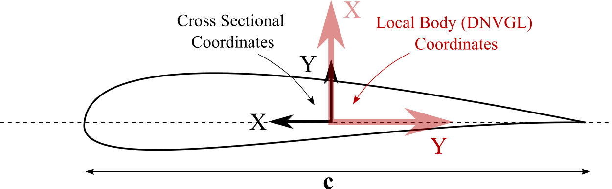
Fig. 112 Difference between the local body coordinate system (DNVGL) and the cross sectional properties coordinate system.
For all other structural bodies (tower, torquetube, substructure) the coordinate system in which the cross sectional structural properties are defined coincides with the local body coordinate system (see Local Blade Coordinate System).
- 1
DNVGL. Guideline for the Certification of Wind Turbines. 2010.