Wind Turbine Controllers
QBlade allows the integration of standard wind turbine controllers to perform aero-servo-hydro-elastic simulations. This is realized via the coupling to a dynamic link library (.dll) which is called every time step by QBlade to update control actions performed on the wind turbine. This is shown in Fig. 116.
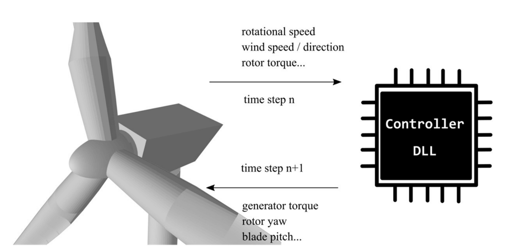
Fig. 116 Controller interaction with QBlade: For each time step, QBlade passes the sensor input and retrieves the control actions demanded from the controller in a predetermined swap array.
Several commonly used controller interfaces are compatible with QBlade. The different types of controller interfaces that QBlade is compatible with are:
Bladed interface: the function DISCON is called
DTU interface: the function update_regulation is called
TUB interface: the function TUBController is called
Since QBlade is compiled as a 64bit software it is only possible to call 64bit compiled controller libraries from QBlade. Open source examples of these three formats are available online. An example for the Bladed-style controller is the NREL1 controller.
An example for a DTU-style controller is the DTU2 controller. An example for the TUB-Style controller is the TUB Controller presented in Perez-Becker et al.3. The QBlade release contains pre-compiled ROSCO, DTU and TUB Controllers.
For these commonly used interfaces the data that is passed between the controller and the simulation in QBlade and its position in the swap array that is used for this communication is already predefined. This means that there are fixed array positions for data such as torque, rpm, pitch angles and tower top accelerations. The specific data that is communicated and its position depends on the controller interface definition and is different between the BLADED-style, DTU-style and TUB-style interfaces.
Location of controller library files
To use a controller library (.dll or .so) in QBlade, place the file in the /ControllerFiles directory within the QBlade installation. When a simulation is initiated, QBlade automatically creates a unique temporary copy of each controller library file in this directory for every simulation instance.
External Library Interface
QBlade also allows to integrate multiple custom dynamic libraries into a simulation. The purpose of a custom library could be the control of an active damping device, the control of a mooring cable length or any other active system which influence can be modeled by the application of a force, moment, a change in mass, pitch torque or a change in mooring line length.
The structure of the External Library Interface consists of an arbitrarily named update() function that is automatically called during every timestep of the simulation (after rampup has been completed). A swap array of floats of arbitrary size is passed to the update() function and retrieved from the update function. The content of the swap array can be freely assigned by the user from all variables that are evaluated from a simulation. In addition the user can also define to what actions should be performed on the turbine, based on the content of the swap array. A minimum working example for the source code of the controller (with focus only on the function definitions) is shown in the section Example for a custom controller library in C.
In Sending Turbine Data to an External Library and Applying External Library Data to the Turbine it is explained how the communication with a controller can be customized.
Adding a Controller or an External Library to a Turbine Definition
A controller library can be included in a turbine definition by selecting the library in the dialog shown in Fig. 117. Depending on which controller interface type is used the appropriate option has to be selected. Furthermore, a controller parameter file has to be selected and loaded by the user. The parameter file is stored in the QBlade project and can be edited by the user once loaded. This if for example useful for setting up an identical turbine with a modified controller parameter (i.e. for control parameter tuning). Controller parameter files edited within QBlade can also be exported to ASCII format.
Any number of custom external libraries can be loaded in the lower part of the dialog shown in Fig. 117. When loading a custom library the user also has to specify the function name that should be called by QBlade as well as the swap array size that will be used for communication between the library and QBlade. Furthermore, a parameter file can optionally be loaded.
Each external library receives an integer identifier, which is later used to pass and receive data to and from its swap array.
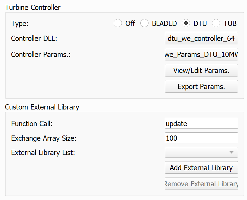
Fig. 117 The controller dialog.
Below is an example for the Turbine Controllers and External Libraries sections in a Turbine Definition ASCII File (.trb). For a predefined controller the controller type, the controller file and its parameter file have to be defined. The three parameters that need to be passed for the external library are the file name (type2_dll), the function name, in this case update2 and the swap array size.
----------------------------------------Turbine Controller-----------------------------------------------------------
3                                        CONTROLLERTYPE     - the type of turbine controller 0 = none, 1 = BLADED, 2 = DTU, 3 = TUB
TUBCon_1.3.9_64Bit                       CONTROLLERFILE     - the controller file name, WITHOUT file ending (.dll or .so ) - leave blank if unused
Control/TUBCon_Params_V1.3.9_NREL5MW.xml PARAMETERFILE      - the controller parameter file name (leave blank if unused)

----------------------------------------External Libraries-----------------------------------------------------------
type2_dll                                LIBFILE_1          - the library file name, WITHOUT file ending (.dll or .so )
update2                                  LIBFUNCTION_1      - the library function name that should be called every timestep
100                                      LIBARRAYSIZE_1     - the library swap array size for data exchange
param.txt                                LIBPARAMETERFILE_1 - the library parameter file name (leave blank if unused)
IMPORTANT:
The controller library (.dll or .so) must always be located in the folder path .\ControllerFiles relative to the QBlade executable.
QBlade is a 64bit code, so the controller dlls must also be compiled for 64bit use.
Defining the Controller or Library Sampling Timestep
By default, if no explicit sampling timestep is specified, QBlade executes the turbine controller or external library at every simulation timestep. In this case, the controller sampling period is identical to the simulation timestep (TIMESTEP).
To decouple the controller update rate from the simulation timestep, the user may specify a custom sampling interval using the parameter SAMPLESTEP. This optional parameter must be defined inside the controller or external-library parameter file:
0.1 SAMPLESTEP
In this example, the controller is executed every 0.1 seconds, regardless of the simulation timestep.
QBlade uses an asynchronous sampling mechanism: the controller operates on its own internal sampling timeline, independent of the simulation timestep. Conceptually, the controller “ticks” at fixed intervals determined by SAMPLESTEP (e.g., 0.0 s, 0.1 s, 0.2 s, …), while the simulation advances with a potentially different timestep. Whenever the simulation time reaches or exceeds the next scheduled controller sampling point, the controller is executed. Between these sampling points, the previously computed controller outputs are held constant using a zero-order hold.
This design intentionally mirrors real industrial PLC-based wind turbine controllers. In an actual turbine, the PLC or embedded controller executes its control loop at a fixed cycle time (for example 25–100 ms), independent of the much faster real-world dynamics of the mechanical and aerodynamic system. The PLC does not update continuously: it samples sensor values at discrete intervals, performs its control computations, and holds its actuator commands constant until the next control cycle. QBlade’s sampling mechanism reproduces this behavior exactly, enabling realistic simulation of discrete-time control systems.
The only restriction is that the sampling step must not be smaller than the simulation timestep (\(dt_\text{sample} < dt_\text{sim}\)). If a smaller sampling step is specified, QBlade will automatically fall back to using the simulation timestep as the effective sampling interval.
Setting a Smooth Controller Ramp
The CONTROLLER_RAMP parameter defines a smooth startup ramp for the controller action. The default value is -1, which activates an automatic ramp duration based on rotor size. If a non-negative value is specified, it is interpreted directly as the ramp duration in seconds.
For the default setting, the ramp time is computed from the rotor diameter as
where \(D\) is the rotor diameter in meters. For vertical-axis turbines, the maximum rotor radius is used to determine the diameter.
During the ramp interval, the controller output is scaled by a half-cosine function so that it increases smoothly from zero to full activity. This avoids an abrupt controller activation at the start of the simulation and can help reduce artificial startup transients and unwanted oscillations. After the ramp time has elapsed, the controller acts at full strength.
The CONTROLLER_RAMP parameter is set in the structural main file. The ramp is only available for the standrad DTU, BLADED or TUB controller interfaces, but not for external libraries, where the user typically has full control over the internal calculations within the library.
2 CONTROLLER_RAMP
Sending Turbine Data to a Wind Turbine Controller
In addition to the standard predefined sensor information that is passed between QBlade and the controller, the user can add additional custom data to the swap array. This is useful for the development of specialized controllers that rely on unconventional sensor input. Depending on the controller format chosen, different positions of the swap array will be unoccupied.
IMPORTANT: The user should know which array entries are unused before adding custom sensors. Otherwise, using this option will lead to unwanted turbine behavior!
To add custom sensors to the swap array of a Predefined Controller (BLADED, DTU or TUB interface), the following table needs to be added to the controller parameter file, the substructure file or the structural model main file (up to the user to decide what is most convenient). The search order in the files is:
structural main file
substructure file
controller parameter stream
The box below shows an exemplary CONTROLLER_IN table. The first column contains the swap array position and the second column the variable name in quotation marks. In the example below the table assigns the variable Time [s] to swap array position [0], the variable Timestep [-] to array position [1] and the variable X_l Acc. BLD_1 pos 1.000 to array position [10]. Note that the full variable name, as shown in any of QBlade’s graphs must be included in the table. If the variable name does not exist (or the data is not stored as part of the simulation) no value is passed to the swap array at the designated position. Also note that the data defined in this table overwrites the standard data that is normally passed to the predefined controller interface.
CONTROLLER_IN
SWAP DATA
0    "Time [s]"
1    "Timestep [-]"
10   "X_l Acc. BLD_1 pos 1.000"
Note that the output of the desired sensor should be enabled in the Main Structural Definition File, and the variable name must exist. Otherwise, zeros will be passed to the controller.
It is also possible to send sectional data using this table. Sectional data requires the inclusion of normalized position information, specifying the relative position along the blade or strut. An example configuration is shown below:
CONTROLLER_IN
SWAP DATA POSITION
0    "Angle of Attack at 0.25c (at section) Blade 1 [deg]" 0.5
1    "Circulation (at section) Blade 2 [m^2/s]" 0.2
10   "Time [s]"
You can directly communicate the timestep size to the controller by using “dt” in the DATA column.
Sending Turbine Data to a Wind Turbine Controller Across Turbine Instances
In multi-turbine or multi-rotor simulations, sensor data from one turbine can be transmitted to the controller of another turbine. To achieve this, append NUM_X to the CONTROLLER_IN keyword, where X is the integer identifier of the target turbine instance. The identifiers start at 0 for the first turbine and increment sequentially up to N-1, where N is the total number of turbines in the simulation.
For instance, to send data to the third turbine in the list (index Turbine[2] in C++ notation), the CONTROLLER_IN table should be configured as follows:
CONTROLLER_IN NUM_2
SWAP DATA
0    "Time [s]"
1    "Timestep [-]"
10   "X_l Acc. BLD_1 pos 1.000"
It is also possible to send data from this turbine controllers SWAP array to the SWAP array of the turbine controller of Turbine[2]. In the example below the SWAP array values from indices 14 and 11 of this turbine are send to the SWAP array of Turbine[2] at the indices 0 and 1.
CONTROLLER_IN NUM_2
SWAP DATA POSITION
0    "SWAP_14"
1    "SWAP_11"
Turbine indices in multi-turbine simulations
While most numberings in QBlade, such as for substructure transition pieces, or for external controllers, start at 1 - the turbine objects are numbered with c++ array notation. The main reason for this is to have consistency with the numbering of turbine objects with the functions in QBlade’s CLI (see: Command Line Interface (CLI) Overview).
Sending Turbine Data to an External Library
Sending custom data to an external library is the same process as sending data to a predefined controller (see Sending Turbine Data to a Wind Turbine Controller), only the keyword for the table changes. In this case we are passing data to the external controller 1, indicated by the keyword EXTERNAL_1_IN. To pass to the second external controller you would use the keyword EXTERNAL_2_IN. It is also possible to send data from the turbine controllers SWAP array to the external library. To do this, simply enter SWAP, followed by the swap array index number:
EXTERNAL_1_IN
SWAP DATA
0    "Time [s]"
1    "Timestep [-]"
2    "SWAP_3"
Note that the output of the desired sensor should be enabled in the Main Structural Definition File and the variable name must exist. Otherwise, zeros will be passed to the controller.
You can directly communicate the timestep size to the controller by using “dt” in the DATA column.
Sending Turbine Data to an External Library Across Turbine Instances
Similar to Sending Turbine Data to a Wind Turbine Controller Across Turbine Instances, it is also possible to send data across turbine instances to an external library. To do this, the user must add the keyword NUM_X, where X represents the identifier of the target turbine instance.
For example, the following configuration sends data to the second external library (EXTERNAL_2) of the fourth turbine (NUM_3) in the simulation:
EXTERNAL_2_IN NUM_3
SWAP DATA
0    "Time [s]"
1    "Timestep [-]"
2    "SWAP_3"
Turbine indices in multi-turbine simulations
While most numberings in QBlade, such as for substructure transition pieces, or for external controllers, start at 1 - the turbine objects are numbered with c++ array notation. The main reason for this is to have consistency with the numbering of turbine objects with the functions in QBlade’s SIL (see Software in Loop (SIL) Overview).
Applying Wind Turbine Controller Data to the Turbine
Swap array data from predefined controller interfaces is automatically applied to perform specific control actions, such as the application of generator torque on the model or control of the blade pitch. The functionality presented hereafter allows to use custom data from the controller swap array to perform specific actions on the turbine.
This functionality is very similar to the function SetExternalAction(), from QBlade’s Software in Loop Interface (SIL), that is described in the Interface Function Documentation. It allows to assign forces, moments, masses and other actions to a turbine in a highly flexible manner.
Again, a table is defined to gather the controller data from the controller swap array. The keyword for this table is CONTROLLER_OUT. The table has a minimum of 6 columns, and an optional 7th column. An exemplary table is shown below:
CONTROLLER_OUT
SWAP  ACTION     ID     POS  DIR  LOCAL  NUM
50    SETLENGTH  MOO_1  1.0  X    true   0
50    SETLENGTH  MOO_2  1.0  X    true   0
Below an overview of the six columns is given:
1: The swap array DATA that will be applied
2: The ACTION that will be performed, based on the data
3: The ID at which the action will be performed
4: The POSITION at which the action will be performed
5: The DIRECTION in which the action is being performed.
6: ISLOCAL whether the direction is defined in local element coordinates or in global coordinates
7: NUM the turbine number on which the action should be performed (num >= 0) or the shared mooring system (num = -1), (default num = -2, this turbine)
The different columns are now further defined:
- DATA
In this column the swapArray index is selected from which data will be used to perform an action.
- Action
- Different actions can be performed, these are:
ADDMASS: adds mass of DATA to a location, in [kg]
ADDFORCE: adds a force of DATA to a location, in [N]
ADDTORQUE: adds a torque of DATA to a location, in [Nm]
SETLENGTH: sets the delta Length of DATA of a cable, in [m]
SETAFC: sets the state of DATA of an AFC element [-]
SETTORQUE: sets the generator torque of DATA, in [Nm]
SETYAW: sets the yaw angle of DATA, in [rad]
SETPITCH: sets the pitch angle of DATA for BLD_X, in [rad]
SETBRAKE: activate the brake [0-off, 1-on]
POSOFFSET : applies a position offset, in [m]
ROTOFFSET : applies a rotation offset, in [rad]
- ID
- The ID is used to identify a certain turbine component, possible IDs and actions that can be performed on them are shown below:
CAB_<X>: applies the action to the guycable with ID <X>. Actions on cables are: SETLENGTH, ADDMASS, ADDFORCE
MOO_<X>: applies the action to the mooring line with ID <X>. Actions on moorings are: SETLENGTH, ADDMASS, ADDFORCE
TRQ: applies the action to the torquetube. Actions on the torquetube are: ADDFORCE, ADDTORQUE, ADDMASS
BLD_<X>: applies the action to blade <X>. Actions on the blades are: ADDFORCE, ADDTORQUE, ADDMASS
STR_<X>_<Y>: applies the action to strut <X> of blade <Y>. Actions on the struts are: ADDFORCE, ADDTORQUE, ADDMASS
AFC_<X>_<Y>: applies the action to AFC <X> of blade <Y>. Actions on the AFC elements are: SETAFC
SUB_<X>: applies the action to the substructure element with ID <X>. Actions on the substructure elements are: ADDFORCE, ADDTORQUE, ADDMASS
JNT_<X>: applies the action to the substructure joint with ID <X>. Actions on the substructure joints are: ADDFORCE, ADDTORQUE, ADDMASS
HUB: applies the action to the free LSS hub node. Actions on the hub node are: ADDFORCE, ADDTORQUE, ADDMASS
HUBFIXED: applies the action to the fixed non-rotating hub node. Actions on the hub node are: ADDFORCE, ADDTORQUE, ADDMASS, POSOFFSET, ROTOFFSET
NAC: applies the action to the nacelle node, located at the tower top, yawing. Actions on the nacelle node are: ADDFORCE, ADDTORQUE, ADDMASS, POSOFFSET, ROTOFFSET
- POSITION
Sets the normalized position [0-1] at which the mass, force or torque is applied. Only has an effect on elements, not on nodes.
- DIRECTION
Specifies the direction along which the force or torque is applied, options are “X”, “Y”, “Z”.
- ISLOCAL
Specifies sets whether the direction is defined in global or local (element or node) coordinates.
- NUM
(OPTIONAL) Specifies if the action should be performed on different turbine in a multi-turbine simulation (num >=0) or on the global mooring system (num == -1), (default: num = -1, this turbine)
Applying External Library Data to the Turbine
Applying custom data from an external library library to the turbine is the same as applying this data from a predefined controller (see Applying Wind Turbine Controller Data to the Turbine) with the exception that the keyword of the table changes to EXTERNAL_<num>_OUT, where <num> is to be replaced by the library integer ID.
EXTERNAL_1_OUT
SWAP  ACTION     ID     POS  DIR  LOCAL  NUM
50    SETLENGTH  MOO_1  1.0  X    true   0
50    SETLENGTH  MOO_2  1.0  X    true   0
Example for a custom controller library in C
The example below shows the source code of a simple external controller library in C-language. Remember that this library should be compiled as 64bit to be compatible with QBlade.
 1#include <stdio.h>
 2#include <cstring>
 3
 4bool firstCall = true;
 5double value;
 6char message_out[1024];
 7
 8//----------------------------------------------------------------
 9// Called once per timestep. This function name needs to match the
10// one that you have assigned as the library function name.
11//----------------------------------------------------------------
12extern "C" __declspec(dllexport) void __cdecl update(float *avrSwap){
13
14        if (firstCall){
15                // example one-time initialization
16                snprintf(message_out,sizeof(message_out),"update call: first call, do some initialization things! Timestep = %f",avrSwap[1]);
17                firstCall = false;
18        }
19        else{
20                // this is an example how some value is computed from the data in the swap array and then
21                // returned in the same swap array at position [50]
22                snprintf(message_out,sizeof(message_out),"update call: successive call, do some calculation things! Time = %f",avrSwap[0]);
23                avrSwap[50] = avrSwap[0]*(-1.0);
24        }
25
26}
27
28//----------------------------------------------------------------
29// Called once before the first `update`. `paramFile` is the full
30// path to your parameter file. Use it to load config.
31// This function should have the same name as the "update"
32// function with "_init" appended to it
33//----------------------------------------------------------------
34extern "C" __declspec(dllexport) void __cdecl update_init(const char *paramFile){
35
36        snprintf(message_out,sizeof(message_out),"_init call: full parameter filename %s",paramFile);
37        // TODO: open paramFile, parse settings, initialize your controller here
38}
39
40//----------------------------------------------------------------
41// if this optional function is defined QBlade calls it
42// automatically to print the output that "update" passes to the
43// message_out variable. This function should have the same name
44// as the "update" function with "_message" appended to it.
45//----------------------------------------------------------------
46extern "C" __declspec(dllexport) void __cdecl update_message(char *outBuf){
47
48        // copy the full 1024-byte buffer, including its terminator
49        std::memcpy(outBuf, message_out, sizeof(message_out));
50}
- 1
NREL. ROSCO. https://github.com/nrel/rosco, 2022. [Online; accessed 2022-05-09].
- 2
DTU. DTUWEC. https://gitlab.windenergy.dtu.dk/OpenLAC/BasicDTUController, 2022. [Online; accessed 2022-05-09].
- 3
S. Perez-Becker, D. Marten, C. N. Nayeri, and C. O. Paschereit. Implementation and Validation of an Advanced Wind Energy Controller in Aero-Servo-Elastic Simulations Using the Lifting Line Free Vortex Wake Model. Energies, 14(3):783, 2021. URL: https://www.mdpi.com/1996-1073/14/3/783, doi:10.3390/en14030783.