Multi Rotor Turbine Assembly
QBlade-EE
This feature is only available in the Enterprise Edition of QBlade.
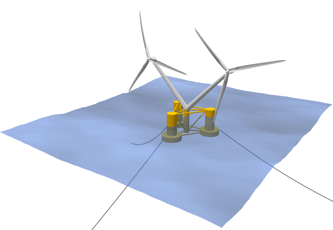
Fig. 114 Visualization of a Multi-Rotor Turbine Assembly.
A turbine with multiple rotors may be defined in the dialog Menu->Turbine Definition->Create a Multi-Rotor Turbine Assembly. A Multi-Rotor Assembly requires the definition of a common substructure, see Substructure Modelling. The common substructure definition must then contain multiple transition pieces (TP_INTERFACE_POS) that may have different orientations (TP_ORIENTATION). If a common substructure is loaded into the Multi Turbine Assembly dialog (see Fig. 115) a turbine from QBlades database (that contains its own structural definition and controller) can be assigned to each of these transition pieces. Multiple transition pieces can be defined by adding _2, _3, _4, …, _N to the respective keywords, such as TP_INTERFACE_POS_2 and TP_ORIENTATION_2, where the appendix _1 can optionally be omitted for the first transition piece and all associated keywords. For any additional transition piece TP_INTERFACE_POS_X, the following keywords may be defined:
REF_COG_POS_X
REF_HYDRO_POS_X
TP_ORIENTATION_X
SUB_MASS_X
SUB_HYDROADDEDMASS_X
SUB_HYDROSTIFFNESS_X
SUB_HYDRODAMPING_X
SUB_HYDROQUADDAMPING_X
SUB_HYDROCONSTFORCE_X
POT_RAD_FILE_X
POT_EXC_FILE_X
POT_SUM_FILE_X
POT_DIFF_FILE_X
AZIOFFSET_X
ROTFACT_X
To connect to a specific transition piece in the SUBCONSTRAINTS table simply use the number X of that transition piece in the TrPID column.
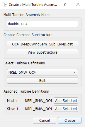
Fig. 115 The Multi-Rotor Assembly Dialog.
Multi Rotor Turbine Assembly Keywords
Two keywords can be used to specify the initial rotor position in a multi-rotor turbine assembly and the relative rotational speed of a rotor in relation to the rotational speed of the master rotor. These keywords have to be defined in the common substructure file.
- AZIOFFSET_X
Offsets the initial azimuthal angle of the rotor by this angle (in °).
120 AZIOFFSET_2- PITCHOFFSET_X
Offsets the initial collective pitch angle of the rotor by this angle (in °).
2 PITCHOFFSET_2- YAWOFFSET_X
Offsets the initial yaw angle of the rotor by this angle (in °).
15 YAWOFFSET_2- ROTFACT_X
Sets the rotational rate of a slave’ rotor in relation to that of the *master rotor. This value is only in effect if the simulation is performed with a fixed rotational rate (see Rotational Speed Settings). If the simulation is carried out with a free rotational rate this value has no effect.
0.9 ROTFACT_2
Multi Rotor Turbine Assembly ASCII File
A Multi Turbine Assembly can be exported or imported in the .mta format. The file content points towards the common substructure file and towards the turbine (.trb) files that are used in the multi-rotor assembly. See an exemplary .mta file below:
----------------------------------------QBlade Multi Turbine Assembly Definition File-------------------------------
Generated with : QBlade IH v2.0.2_alpha windows
Archive Format: 310003
Time : 18:25:50
Date : 04.07.2022

----------------------------------------Object Name-----------------------------------------------------------------
double_OC4                               OBJECTNAME         - the name of the multi-rotor turbine object

----------------------------------------Assembly Definition---------------------------------------------------------
OC4_DeepCWindSemi_Sub_LPMD.dat           SUBSTRUCTURE       - the path of the common substructure file that is used in this multi turbine assembly
NREL_5MW_OC4.trb                         MASTER             - the master turbine of the assembly
NREL_5MW_OC4.trb                         SLAVE_1            - the slave turbine(s) of the assembly