Simulation Module Overview

Fig. 135 The simulation module symbol in the QBlade main tool bar.
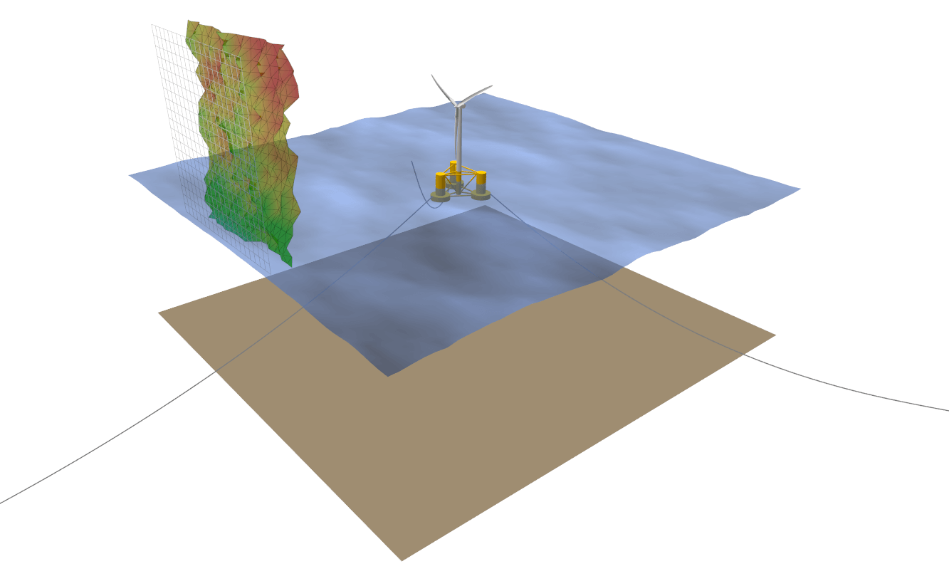
Fig. 136 Visualization of an aero-hydro-servo-elastic simulation in QBlade.
To define a simulation of a turbine object several simulation parameters and boundary conditions need to be defined. The following list gives an overview:
Simulation length & time step size
Structural solver
Wind boundary conditions
Wave & current boundary conditions
Environmental parameters: density, gravity, etc.
Simulations can either be defined through the turbine simulation dialog, or directly by creating or modifying simulation definition (.sim) files.
Simulation Definition
Setting up a simulation in QBlade is handled through the dialog shown below:
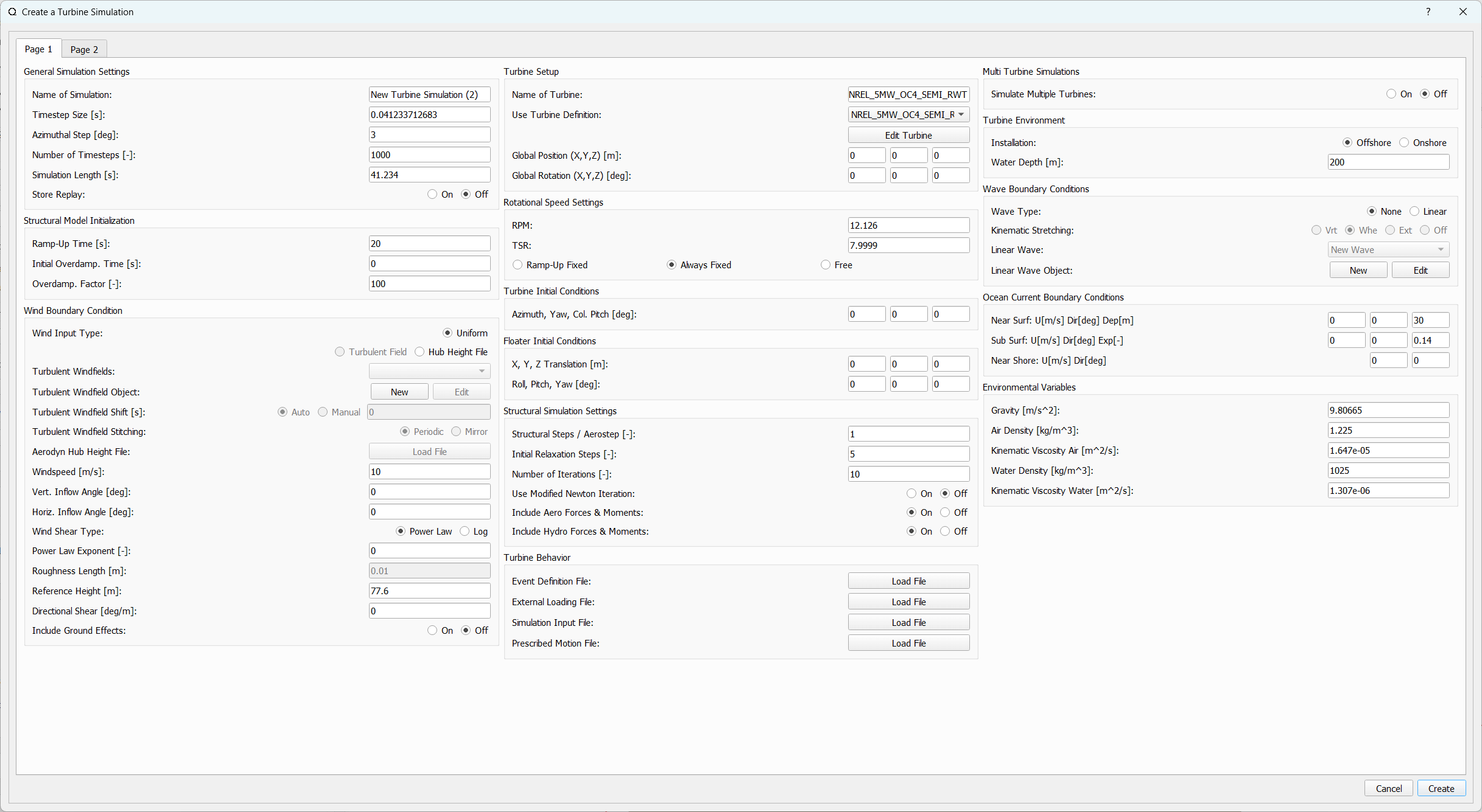
Fig. 137 Page 1 of the simulation definition dialog (click to enlarge).
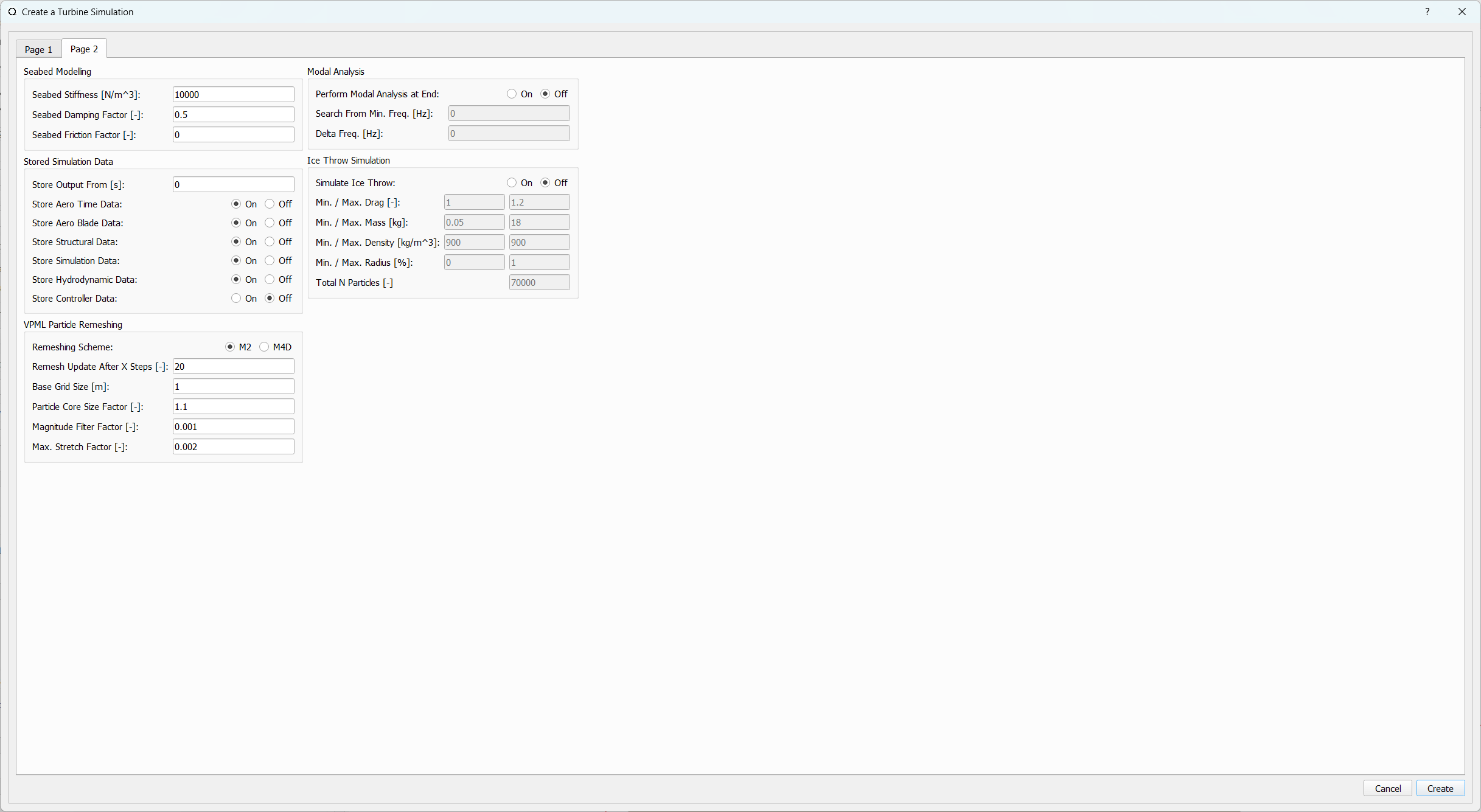
Fig. 138 Page 2 of the simulation definition dialog (click to enlarge).
Below, an overview of the different dialog sections and each editable parameters is given. If you are looking for a specific parameter from the dialog it is suggested to use the search function of the documentation to find it quickly. Also note that each of the parameters described in the following has an equivalent keyword within the Simulation Definition ASCII File.
General Simulation Settings
Name of Simulation: A unique name to identify the simulation object
Timestep Size / Azimuthal Step: Both values are interconnected through the turbine RPM setting
Number of Timesteps / Simulation Length: Both values are interconnected through the TimestepSize setting
Store Replay: A replay of the simulation is created by storing all position and wake data for every timestep.
Structural Model Initialization
These field are only editable if the selected turbine object has a structural model definition.
Ramp-Up Time: The (structural) simulation is ramped-up over the specified time. This part of the simulation does not generate data and is not stored.
Initial Overdamp. Time: For the specified time the model Rayleigh damping is increased by the factor Overdamp. Factor. If the value is 0 the overdamping is active during ramp-up, any negative value disables overdamping of the model.
Overdamp. Factor: During the overdamping time all model damping values are increased by this factor.
Wind Boundary Condition
Wind Input Type: Sets the wind input type. Options are Uniform Wind Field, Turbulent Wind Field and Hub Height File.
Turbulent Windfields: In this ComboBox all Windfields that are stored in the database are listed.
Turbulent Windfield Object: These buttons allow to generate a new Windfield or to edit an existing one.
Turbulent Windfield Shift: The currently selected Windfield may be shifted in time (to start at another time than t=0s), if Auto is chosen the Windfield is shifted by the rotor diameter divided by the mean freestream velocity to fully immerse the rotor at the start of a simulation..
Turbulent Windfield Stitching: If the simulation time is larger than the Windfield length the Windfield is either repeated (Periodic) or mirrored (Mirror) at the end of its timeseries.
Aerodyn Hub Height File: This enables to load a hub height file from the file system to be assigned to this simulation.
Windspeed: Set the windspeed if Wind Input Type is set to Uniform.
Vert. Inflow Angle: Set the vertical inflow angle if Wind Input Type is either Uniform or Turbulent Field.
Horiz. Inflow Angle: Set the horizontal inflow angle if Wind Input Type is either Uniform or Turbulent Field.
Wind Shear Type: Set the windshear type if the wind input type is Uniform or the turbulent windfield is imported.
Power Law Exponent: Set the Coefficient for a Power Law wind profile.
Roughness Length: Set the Roughness Length for a Log Profile..
Reference Height: Set the Reference Height for the wind profiles.
Directional Shear: Set a directional shear. The shear is assumed to be 0.0 at the Reference Height.
Include Ground Effects: Interludes the modelling of Ground Effects, see Ground Effect.
Turbine Setup
Name of Turbine: Define a name for the turbine simulation object.
Use Turbine Definition: Use the selected turbine definition object from the data base in this simulation object.
Global Position (X,Y,Z): Set the global position of the wind turbine for this simulation.
Global Rotation (X,Y,Z): Set the global rotation of the wind turbine for this simulation. In the case of a floating turbine being simulated the global rotation also rotates the mooring line connections to the ground.
Rotational Speed Settings
RPM / TSR: Both values are interconnected through the rotor size and current windspeed.
The following options are related to the RPM control for this simulation. For turbine definition object without a structural definition the RPM is always constant if no Simulation Input File is defined. For turbine definition objects with a structural definition the following options are avaliable:
Ramp-Up Fixed: The RPM is fixed only during the ramp-up time of the simulation so that when the simulation starts the rotor is operating at the chosen RPM. During the simulation time the rotor rotation is governed by the balance of aerodynamic- and generator torque. This is the recommended setting for simulations that contain a Controller.
Always Fixed: The RPM is fixed for the total duration of the simulation to the chosen RPM.
Free: For ramp-up and simulation time the rotor rotation is governed by the balance of aerodynamic- and generator torque.
Turbine Initial Conditions
Azimuth, Yaw, Col. Pitch: Sets the initial azimuthal rotor angle, yaw angle and collective pitch angle for the simulation.
Floater Initial Conditions
These edits are only enabled if a wind turbine with a floating substructure is simulated. The initial floater conditions can be used to setup decay tests for specific DOF’s or to place the floater closer to its final equilibrium position to speed-up initial transients.
X, Y, Z Translation: Sets the initial displacement for the floater.
Roll, Pitch, Yaw: Sets the initial rotation of the floater.
Structural Simulation Settings
Structural Steps / Aerostep: Sets how many structural steps will be evaluated per global timestep. If multiple structural steps are evaluated per global timestep the aerodynamic loading is assumed to be constant.
Initial Relaxation Steps: An initial iterative relaxation is performed, taking into account only gravitational forces.
Number of Iterations: Set the number of iterations for the iterative time steppers, such as the HHT.
Include Aero Forces & Moments: Toggles if aerodynamic forces are projected onto the structural model definition.
Include Hydro Forces & Moments: Toggles if hydrodynamic forces are projected onto the structural model definition.
Turbine Events and Operation
In this section special events, external loading, prescribed motion and prescribed operation can be defined for a turbine definition. Below exemplary files are shown for each file type:
Event Definition File
An event is defined by a combination of Keywords and values. The following list gives an overview of the available event types. Events can only be defined if the turbine definition has a structural definition. Multiple events may be defined in a single file. The events override any events / control that is returned via the controller exchange array:
30 FAILGRID: At time 30 s, the generator moment is set to 0 Nm.
30 SETBRAKE: At time 30 s, the brake is engaged.
30 1.5 FAILPITCH_1: At time 30 s, the pitch rate of blade nr. 1 is set to a maximum rate of 1.5 deg/s
30 90 1.5 PITCHTO: At time 30 s, the collective pitch rate is set to 1.5deg/s until 90 deg are reached.
30 90 1.5 YAWTO: At time 30 s, the yaw rate is set to 1.5deg/s until 90 deg are reached.
30 FAILBLADE_1: At time 30 s, blade nr. 1 is released from the hub, by deactivating the respective structural constraint.
30 FAILCAB_1: At time 30 s, the cable with the CABID 1 is removed.
30 FAILMOO_1: At time 30 s, the mooring line with the MOOID 1 is removed.
30 FAILCST_1: At time 30 s, the constraint with the CSTID 1 is deactivated.
The events FAILMOO and FAILCST may also be defined in the Multi Turbine Global Mooring System file. If defined there, these events are applied onto the mooring lines or constraints of the shared mooring system.
External Loading File
A user defined loading timeseries can be applied to the turbine during simulation via this file format, multiple loading timeseries may be appended into a single file. The nomenclature in the file is as follows:
<SensorName> <localflag>
<time1> <fx1> <fy1> <fz1> <mx1> <my1> <mz1>
<time2> <fx2> <fy2> <fz2> <mx2> <my2> <mz2>
Sensor naming is the same as in the main file for the sensor outputs (see Loading Data and Sensor Locations). The local flag (local, global) defines if the loads are applied in the Global Coordinate System or in the Local Body Coordinate Systems or Local Sensor Coordinate Systems. QBlade interpolates linearly the loads between time stamps. External load time series for multiple sensors can be appended into a single file.
Furthermore, the user can specify the following <SensorNames> to which the loading will be applied:
TWR_<Y>: The load will be applied to the tower at the normalized position <Y>*
TRQ_<Y>: The load will be applied to the torquetube at the normalized position <Y>.
BLD_<X>_<Y>: The load will be applied to blade <X> at the normalized position <Y>.
STR_<X>_<Y>_<Z>: The load will be applied to strut <X> of blade <Y> at the normalized position <Z>.
SUB_<X>_<Y>: The load will be applied to the substructure element with ID <X> at the normalized position <Y>.
JNT_<X>: The load will be applied to the substructure joint with ID <X>.
CAB_<X>_<Y>: The load will be applied to the cable with ID <X> at the normalized position <Y>.
MOO_<X>_<Y>: The load will be applied to the mooring line with ID <X> at the normalized position <Y>.
HUB: The load will be applied to the free LSS hub node, in the rotating hub coordinate system.
HUBFIXED: The load will be applied to the fixed non-rotating hub node.
NAC: The load will be applied to the nacelle node, located at the tower top, yawing.
GENERATOR: The <mx> torque will be applied to the generator side of the drivetrain, all other force components (<fx> <fy> <fz> <my> <mz>) are ignored.
This exemplary file applies an impulsive load of 1e8 N along the global x-direction to the tower at 50% height. The loads are interpolated in time, so the x-loading rises from 0 N at 19.8s linearly to 1e8 N at 20s and drops off to 0 N at 20.2s:
TWR_0.5 false
19.8    0       0       0       0       0       0
20      1e8     0       0       0       0       0
20.2    0       0       0       0       0       0
Simulation Input File
The turbine operation can be prescribed using a file of the following format. Turbine definition with or without a structural definition can be subjected to prescribed operation. QBlade interpolates linearly the loads between time stamps.
Time    RPM     Yaw     PitchB1 PitchB2 ...     PitchBN AFC1_B1 AFC2_B2 ...     AFCN_BN
0       1       11      0       0       ...     0       0       0       ...     0
5       2       11      0       0       ...     0       0       0       ...     0
10      4       11      0       5       ...     0       0       0       ...     0
15      7       11      0       10      ...     0       0       0       ...     0
20      11      11      0       17      ...     0       0       0       ...     0
25      12      11      0       27      ...     0       0       0       ...     0
30      13      11      0       40      ...     10      0       0       ...     0
35      12      11      0       40      ...     20      0       0       ...     0
40      11      11      0       40      ...     30      0       0       ...     0
45      11      11      0       40      ...     40      0       0       ...     0
50      11      11      0       40      ...     40      0       0       ...     0
Prescribed Motion File
The translation and rotation of the ground, where the tower bottom of the wind turbine is constrained, can be prescribed using a prescribed motion file of the following format. The translation and rotation is applied to the “ground” to which a bottom fixed turbine is directly connected.
If a floating wind turbine is simulated the prescribed motion will only affect elements that are constrained to the seabed (typically the mooring line anchors). By using the keyword FIXEDFLOATER (see Miscellaneous Substructure Parameters) in the turbine substructure definition it is also possible to prescribe the translation/rotation of the floater directly.
Time    TransX  TransY  TransZ  RotX    RotY    RotZ
0       1       11      0       0       0       0
5       2       11      0       0       0       0
10      4       11      0       5       0       0
15      7       11      0       10      0       0
20      11      11      0       17      0       0
25      12      11      0       27      0       0
30      13      11      0       40      10      10
35      12      11      0       40      20      20
40      11      11      0       40      30      30
45      11      11      0       40      40      40
50      11      11      0       40      40      40
Multi Turbine Simulations
QBlade-EE
This feature is only available in the Enterprise Edition of QBlade.
If enabled multiple turbines may be added to a single simulation object and their wake interaction can be evaluated. Find more information in the section Multi Turbine Simulation Setup.
Turbine Environment
Installation: The user can chose between Offshore and Onshore installation. If Offshore is selected the user must also specify the water depth.
Water Depth: Sets the water depth for an offshore simulation.
Wave Boundary Conditions
These edits are only enabled if Offshore installation is selected.
Wave Type: Toggles if a linear wave should be included in the simulation.
Kinematic Stretching: Choose the Kinematic Stretching type if a linear wave is selected.
Vertical Weight: Interpolates between Vertical stretching and Wheeler stretching to provide a controlled modeling envelope for near-surface kinematics and resulting Morison loads (see: Kinematic Stretching). The Vertical Weight parameter only has an effect when Vertical stretching is chosen as kinematic stretching.
Linear Wave: A wave from QBlades database can be selected.
Linear Wave Object: The currently selected wave object can be edited or a new wave object can be created.
Ocean Current Boundary Conditions
Near Surf: U, Dir, Dep: Sets velocity, direction and depth parameters for Near Surface Currents, see Currents.
Sub Surf: U, Dir, Exp: Sets velocity, direction and exponent parameters for Sub Surface Currents, see Currents.
Near Shore: U, Dir: Sets velocity and direction for Near Shore Currents, see Currents.
Environmental Variables
The user can set the environmental parameters that are used during the simulation and for the evaluation of several quantities such as Reynolds Number or Keulegan-Carpenter Number. The list of environmental parameters is shown below:
Gravity
Air Density
Kinematic Viscosity (Air)
Water Density
Kinematic Viscosity (Water)
Seabed Modelling
To prevent the mooring lines from penetrating the seabed, the seabed is modelled as vertically oriented spring/dampers that act on the mooring line elements that are in contact with the seabed. The model implemented is highly similar to the work of Hall1. For more details see the theory section: Seabed.
Seabed Stiffness: The linear foundation spring stiffness coefficient for the seabed. It calculates the vertical restorative normal force based on the depth of the element’s penetration into the soil.
Seabed Damping: The absolute viscous damping coefficient of the seabed soil. It acts purely in the vertical direction, applying a resistive pressure proportional to the element’s vertical penetration velocity.
Seabed Friction Coefficients (Axial & Transverse): The kinetic Coulomb friction coefficients (\(\mu_k\)). They act in the horizontal plane, opposite to the direction of line movement. The friction force is calculated as a fraction of the vertical normal contact force. It is split into Axial (sliding along the cable’s length) and Transverse (dragging perpendicular to the cable) components.
Seabed Static/Kinetic Friction Scale: A dimensionless multiplier applied to the kinetic friction coefficients to define the static breakout friction limit (\(\mu_s = \mu_k \times \text{Scale}\)).
Seabed Friction Break Velocity: The critical ramp-up velocity (\(v_c\)) [m/s]. To prevent numerical instability, friction ramps linearly from zero up to the static limit while the cable velocity is below this threshold, and saturates at the kinetic limit once exceeded.
Stored Simulation Data
The user can choose here to only store a certain type of simulation data (to limit the project file or data export size. Furthermore, the user can choose to store simulation data only after a certain time has passed, to remove transients from the datasets.
Store Output From: Simulation Data is only stored after the defined simulation time has passed.
Store Aero Time Data: Toggles if this data type is stored. (All data that is shown in the Aerodynamic Time Graph).
Store Aero Blade Data: Toggles if this data type is stored. (All data that is shown in the Aerodynamic Blade Graph).
Store Structural Data: Toggles if this data type is stored. (All data that is shown in the Structural Time Graph).
Store Simulation Data: Toggles if this data type is stored. (All data that is shown in the Simulation Graph).
Store Hydrodynamic Data: Toggles if this data type is stored. (All data that is shown in the Hydrodynamic Time Graph).
Store Controller Data: Toggles if this data type is stored. (All data that is shown in the Controller Time Graph).
Store DWM Wake Data: Toggles if this data type is stored. (All data that is shown in the DWM Graph).
Results Filter: To store only a subset of the generated data, a Results Filter can be applied. Users can specify a list of the variable names that should be stored. Below is an example of variable names for the Results Filter. When a user specified a Results Filter only the variables specified within the filter file, in the order in which they are specified, are stored. This is an effective way to prepare simulation data for post-processing and to reduce the memory consumption during large batch runs of simulations.
Time [s]
Abs Inflow Vel. at Hub [m/s]
Aero. Power [W]
Gen. Elec. Power [W]
Gen. HSS Torque [Nm]
X_c RootBend. Mom. (IP) BLD_1 [Nm]
Y_c RootBend. Mom. (OOP) BLD_1 [Nm]
Z_c RootBend. Mom. BLD_1 [Nm]
X_tb Mom. TWR Bot. Const. [Nm]
Y_tb Mom. TWR Bot. Const. [Nm]
Z_tb Mom. TWR Bot. Const. [Nm]
X_n For. Nac. Const. [N]
Y_n For. Nac. Const. [N]
Z_n For. Nac. Const. [N]
X_n Mom. Nac. Const. [Nm]
Y_n Mom. Nac. Const. [Nm]
Z_n Mom. Nac. Const. [Nm]
VPML Particle Remeshing
QBlade-EE
This feature is only available in the Enterprise Edition of QBlade.
Free wake filaments may be converted into vortex particles. The following parameters govern the treatment of free vortex particles during a simulation.
Remeshing Scheme
Remesh Update After X Steps
Base Grid Size
Particle Core Size Factor
Magnitude Filter Factor
Max. Stretch Factor
Modal Analysis
QBlade-EE
This feature is only available in the Enterprise Edition of QBlade.
When activated, a modal analysis is performed at the end of the simulation. This process linearizes the mass, stiffness, and damping matrices around the turbine’s operating point. Aerodynamic forces are included as a Jacobian matrix, and geometric stiffness effects are added if enabled in the wind turbine definition. A generalized eigenvalue problem (GEP) is then set up and solved. The modal analysis is carried out after the end of the simulation, when the rotor reaches its initial azimuthal position, facilitating the comparison of mode shapes across different operating points, such as for generating automated Campbell Diagrams.
Perform Modal Analysis at end: Toggles if a modal analysis is performed at the end of the simulation.
Search From Min. Freq.: Only modeshapes with an Eigen frequency above this value are stored.
Delta Freq.: Only modeshapes that are spaced apart by this value are stored.
Number Modes: The number of modes (starting from the lowest frequency) that will be stored.
When a model analysis has successfully been conducted, the modeshapes can be inspected in the GUI (see Fig. 140). For this purpose the currently visualized modeshape can be changed in the Modal Analysis Dock Window (see Fig. 139). In the menu the currently displayed mode can be changed (Number). Furthermore, the amplification of the mode shape (Amp), and the scaling of the rotational modal displacements, in relation to the translational modal displacements, can be set (R.Scale). Lastly, it is also possible to plot the Real, Imaginary, Magnitude of Phase of the mode (Show).

Fig. 139 The Modal Analysis Dock Window
By setting up multiple simulations, at different windspeeds or rotational speeds, it is also possible to create a Campbell diagram for a wind turbine. This is explained in the section Creating Campbell Diagrams.

Fig. 140 Visualization of a modeshape
Dynamic Wake Meandering
Here the user can choose which wake summation method shall be applied to overlapping wakes of the Dynamic Wake Meandering Model. The different options are:
Dominant Wake: The combined wake velocity is equal to the velocity of the wake with the largest velocity deficit (induction)
Sum of Squares: The wake induced velocities are summed up by the sum of squares method.
Vector Sum: The wake induced velocities are summed up by linear vector addition.
Ice Throw Simulation
QBlade-EE
This feature is only available in the Enterprise Edition of QBlade.
A simulation of ice throw, shed from the rotor, can be performed in QBlade, see Lennie and Marten2. The following parameters govern the range of the randomized uniform distributions of ice particle properties. The distribution of landed ice particles can then be exported to generate iso-risk contours for the localized individual risk (LIRA) of a person being hit by an ice throw event.
Simulate Ice Throw: Toggles if an Ice Throw Simulation is carried out.
Min. / Max. Drag: Sets the range of drag values for the generated ice particles.
Min. / Max. Mass: Set the range of masses for the generated ice particles.
Min. / Max. Density: Set the range of density for the generated ice particles.
Min. / Max. Radius: Set the range of ice particle release positions (in % of rotor radius).
Total N Particles: Set the total number of ice particles that are generated during the simulation. This number will be evenly distributed over all timesteps of the simulation.
Simulation Definition ASCII File
Simulation objects can be exported into the text based .sim format. When a simulation object is exported into the .sim format, the associated turbine .trb file is automatically generated and exported. See an exemplary .sim file below:
----------------------------------------QBlade Simulation Definition File------------------------------------------
Generated with : QBlade CE v2.0.7-release_candidate_beta windows
Archive Format: 310023
Time : 21:27:48
Date : 15.05.2024

----------------------------------------Object Name-----------------------------------------------------------------
OC4_Semi_Test                            OBJECTNAME         - the name of the simulation object

----------------------------------------Simulation Type-------------------------------------------------------------
1                                        ISOFFSHORE         - use a number: 0 = onshore; 1 = offshore

----------------------------------------Turbine Parameters---------------------------------------------------------
multiple turbines can be added by adding multiple definitions encapsulated with TURB_X and END_TURB_X, where X must start at 1

TURB_1
    NREL_5MW_OC4_SEMI_RWT/NREL_5MW_OC4_SEMI_RWT.trb TURBFILE           - the turbine definition file that is used for this simulation
    NREL_5MW_OC4_SEMI_RWT                TURBNAME           - the (unique) name of the turbine in the simulation (results will appear under this name)
    15.00                                INITIAL_YAW        - the initial turbine yaw in [deg]
    15.00                                INITIAL_PITCH      - the initial collective blade pitch in [deg]
    40.00                                INITIAL_AZIMUTH    - the initial azimuthal rotor angle in [deg]
    1                                    STRSUBSTEP         - the number of structural substeps per timestep (usually 1)
    5                                    RELAXSTEPS         - the number of initial static structural relaxation steps
    0                                    PRESCRIBETYPE      - rotor RPM prescribe type (0 = ramp-up; 1 = whole sim; 2 = no RPM prescribed)
    7.000                                RPMPRESCRIBED      - the prescribed rotor RPM [-]
    5                                    STRITERATIONS      - number of iterations for the time integration (used when integrator is HHT or Euler)
    0                                    MODNEWTONITER      - use the modified newton iteration?
    1                                    INCLUDEAERO        - include aerodynamic forces?
    1                                    INCLUDEHYDRO       - include hydrodynamic forces?
    0.00                                 GLOBPOS_X          - the global x-position of the turbine [m]
    0.00                                 GLOBPOS_Y          - the global y-position of the turbine [m]
    0.00                                 GLOBPOS_Z          - the global z-position of the turbine [m]
    0.00                                 GLOBROT_X          - the global x-rotation of the turbine [deg]
    0.00                                 GLOBROT_Y          - the global y-rotation of the turbine [deg]
    0.00                                 GLOBROT_Z          - the global z-rotation of the turbine [deg]
                                         EVENTFILE          - the file containing fault event definitions (leave blank if unused)
                                         LOADINGFILE        - the loading file name (leave blank if unused)
                                         SIMFILE            - the simulation file name (leave blank if unused)
                                         MOTIONFILE         - the prescribed motion file name (leave blank if unused)
    4.00                                 FLOAT_SURGE        - the initial floater surge [m]
    3.00                                 FLOAT_SWAY         - the initial floater sway [m]
    6.00                                 FLOAT_HEAVE        - the initial floater heave [m]
    7.00                                 FLOAT_ROLL         - the initial floater roll [deg]
    5.00                                 FLOAT_PITCH        - the initial floater pitch [deg]
    9.00                                 FLOAT_YAW          - the initial floater yaw [deg]
END_TURB_1

----------------------------------------Simulation Settings-------------------------------------------------------
0.050000                                           TIMESTEP           - the timestep size in [s]
1000                                               NUMTIMESTEPS       - the number of timesteps
50.000                                             RAMPUP             - the rampup time for the structural model
0.000                                              ADDDAMP            - the initial time with additional damping
100.000                                            ADDDAMPFACTOR      - for the additional damping time this factor is used to increase the damping of all components
0.000                                              WAKEINTERACTION    - in case of multi-turbine simulation the wake interaction start at? [s]

----------------------------------------Wind Input-----------------------------------------------------------------
0                                                  WNDTYPE            - use a number: 0 = steady; 1 = windfield; 2 = hubheight
                                                                                                   WNDNAME            - wind file name: TurbSim (.inp), Mann (.man), hub-height (.hht) or binary field (.bts); leave empty if unused. If an .inp is given and a matching .bts exists, the .bts is used
0                                                  STITCHINGTYPE      - the windfield stitching type; 0 = periodic; 1 = mirror
true                                               WINDAUTOSHIFT      - the windfield shifting automatically based on rotor diameter [bool]
0.00                                               SHIFTTIME          - the windfield is shifted by this time if WINDAUTOSHIFT = 0
10.00                                              MEANINF            - the mean inflow velocity, overridden if a windfield or hubheight file is use
0.00                                               HORANGLE           - the horizontal inflow angle
0.00                                               VERTANGLE          - the vertical inflow angle
0                                                  PROFILETYPE        - the type of wind profile used (0 = Power Law; 1 = Logarithmic)
0.000                                              SHEAREXP           - the shear exponent if using a power law profile, if a windfield is used these values are used to calculate the mean wake convection velocities
0.010                                              ROUGHLENGTH        - the roughness length if using a log profile, if a windfield is used these values are used to calculate the mean wake convection velocities
0.00                                               DIRSHEAR           - a value for the directional shear in deg/m
115.63                                             REFHEIGHT          - the reference height, used to construct the BL profile
false                                              GROUNDEFFECT       - should the ground effect be included (for vortex lines and particles)

----------------------------------------Ocean Depth, Waves and Currents-------------------------------------------
the following parameters only need to be set if ISOFFSHORE = 1
250.00                                             WATERDEPTH         - the water depth
New_Wave.lwa                                       WAVEFILE           - the path to the wave file, leave blank if unused
1                                                  WAVESTRETCHING     - the type of wave stretching, 0 = vertical, 1 = wheeler, 2 = extrapolation, 3 = none
1                                                  VERTWEIGHT         - vertical to wheeler blending factor: 1 = pure vertical, 0 = pure wheeler, only active if WAVETRETCHING = 0
10000.00                                           SEABEDSTIFF        - the vertical seabed stiffness [N/m^3]
2000.00                                            SEABEDDAMP         - a linear damping coefficient for the vertical seabed contact [N*s/m^3]; applied proportional to vertical penetration velocity
0.10                                               SEABEDFRICTAXIAL   - seabed axial kinematic friction coefficient (mu_k_a) [-]; defines the Coulomb sliding friction along the seafloor (typically 0.2 to 1.0)
0.10                                               SEABEDFRICTTRANS   - seabed transverse kinematic friction coefficient (mu_k_t) [-]; defines the Coulomb sliding friction along the seafloor (typically 0.2 to 1.0)
1.00                                               SEABEDFRICTSCALE   - static/dynamic friction scale [-]; mu_s = mu_k * scale (1.0 = no breakout, > 1.0 increases low-speed/breakout resistance)
0.0500                                             SEABEDFRICTVEL     - seabed friction break velocity v_c [m/s]; threshold for kinetic sliding (MoorDyn FricDamp = 1.0 / v_c)
0.00                                               SURF_CURR_U        - near surface current velocity [m/s]
0.00                                               SURF_CURR_DIR      - near surface current direction [deg]
30.00                                              SURF_CURR_DEPTH    - near surface current depth [m]
0.00                                               SUB_CURR_U         - sub surface current velocity [m/s]
0.00                                               SUB_CURR_DIR       - sub surface current direction [deg]
0.14                                               SUB_CURR_EXP       - sub surface current exponent
0.00                                               SHORE_CURR_U       - near shore (constant) current velocity [m/s]
0.00                                               SHORE_CURR_DIR     - near shore (constant) current direction [deg]

----------------------------------------Global Mooring System------------------------------------------------------
                                                                                                MOORINGSYSTEM      - the path to the global mooring system file, leave blank if unused

----------------------------------------Dynamic Wake Meandering----------------------------------------------------
0                                                  DWMSUMTYPE         - the dynamic wake meandering wake summation type: 0 = DOMINANT; 1 = QUADRATIC; 2 = LINEAR

----------------------------------------Environmental Parameters---------------------------------------------------
1.22500                                            DENSITYAIR         - the air density [kg/m^3]
0.000016470                                        VISCOSITYAIR       - the air kinematic viscosity
1025.00000                                         DENSITYWATER       - the water density [kg/m^3]
0.000001307                                        VISCOSITYWATER     - the water kinematic viscosity [m^2/s]
9.806650000                                        GRAVITY            - the gravity constant [m/s^2]

----------------------------------------Output Parameters----------------------------------------------------------
20.00000                                           STOREFROM          - the simulation stores data from this point in time, in [s]
false                                              STOREREPLAY        - store a replay of the simulation (warning, large memory will be required) [bool]
true                                               STOREAERO          - should the aerodynamic data be stored [bool]
true                                               STOREBLADE         - should the local aerodynamic blade data be stored [bool]
true                                               STORESTRUCT        - should the structural data be stored [bool]
true                                               STORESIM           - should the simulation (performance) data be stored [bool]
true                                               STOREHYDRO         - should the controller data be stored [bool]
false                                              STORECONTROLLER    - should the hydrodynamic data be stored [bool]
false                                              STOREDWM           - should the dynamic wake meandering (DWM) data be stored [bool]
                                                                                                FILTERFILE         - filename of the results data filter file, leave blank if unused

----------------------------------------Modal Analysis Parameters--------------------------------------------------
false                                              CALCMODAL          - perform a modal analysis (only single turbine simulations) [bool]
false                                              USEMBC             - apply the multi blade coordinate transformation (MBC) during the modal analysis [bool]
0.00000                                            MINFREQ            - store Eigenvalues, starting with this frequency
0.00000                                            DELTAFREQ          - omit Eigenvalues that are closer spaced than this value
100.00000                                          NUMFREQ            - set the number of Eigenmodes and Eigenvalues that will be stored
Multi-Threaded Batch Analysis
QBlade-EE
This feature is only available in the Enterprise Edition of QBlade.
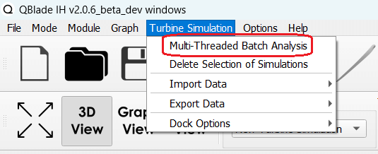
Fig. 141 The multi-threaded batch menu option.
Multiple simulations can be evaluated in a parallel batch queue through the dialog Menu->Turbine Simulation->Multi-Threaded Batch Analysis. The simulations are selected from a list in the dialog (see Fig. 142). After choosing the number of parallel threads the batch analysis starts by clicking the Start Batch button.
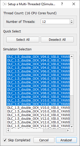
Fig. 142 The multi-threaded batch analysis dialog.
- 1
M. Hall. Efficient modelling of seabed friction and multi-floater mooring systems in moordyn. Proceedings of the 12th European Wave and Tidal Energy Conference, 2017:1, 2017. URL:, doi:.
- 2
S. Lennie, M. Dominin and D. Marten. Development of ice throw model for wind turbine simulation software qblade. AIAA Scitech 2019 Forum, 2019. URL: https://arc.aiaa.org/doi/abs/10.2514/6.2019-1800, doi:10.2514/6.2019-1800.