Velocity Cut-Planes
A velocity cut-plane can be used to extract velocity distributions from either a simulation if the wind turbine wake model is either the Free Vortex Wake model, or the Dynamic Wake Meandering Model.
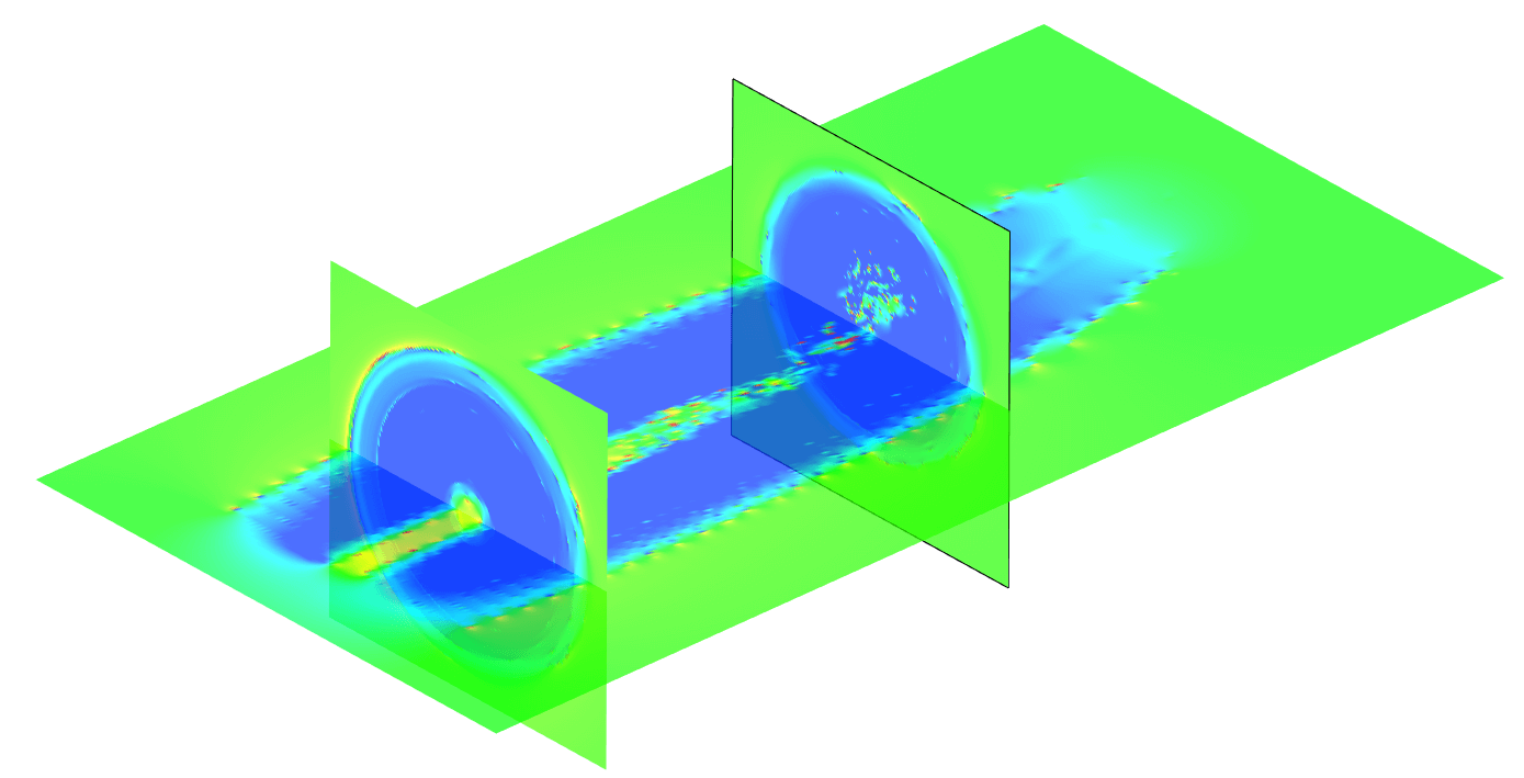
Fig. 143 Wake velocity distribution generated from a LLFVW simulation.
Generating Cut-Planes
In the Cut-Plane Dialog, found in the Dock Window of the Turbine Simulation module in QBlade (see Fig. 144), one or multiple cut planes can be generated by defining the plane center, its dimensions and orientation. If the replay (see General Simulation Settings) of a simulation has been stored it is also possible to automatically generate cut planes for each timestep of a simulation, after the simulation is finished, by choosing the + all next option. The % x box allows to selectively only generate cut-planes when mod(timestep,x) = 0. The from Timestep box allows to choose the timestep from which the cut-planes should be generated. The checkbox rotor fixed allows to automatically rotate a cut plane definition with the current rotor position.
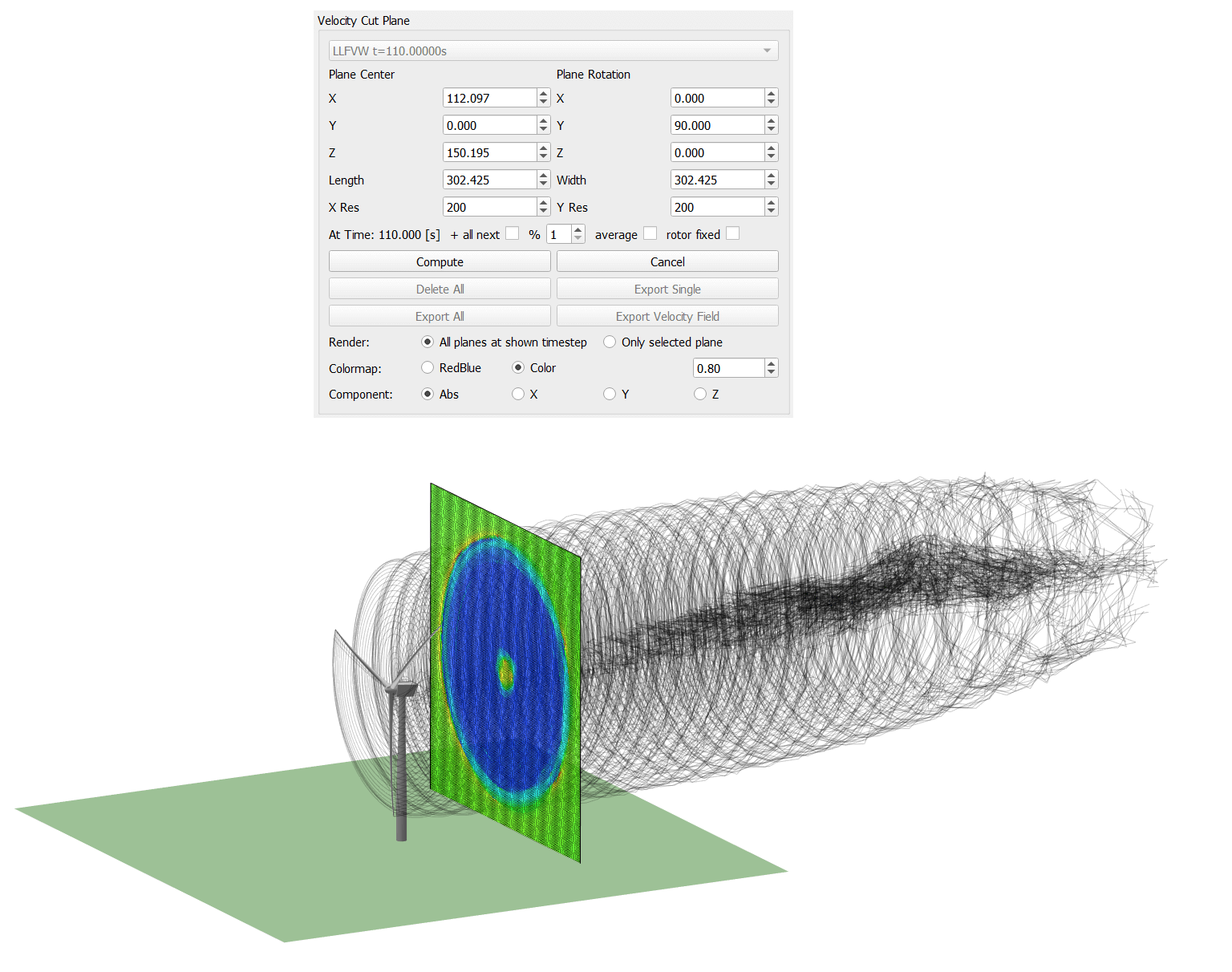
Fig. 144 The cut-plane options dialog.
Furthermore, the dialog allows to export three dimensional velocity fields, or to generate fully turbulent wind fields, sampled from a simulation.
Export Velocity Fields
A three dimensional velocity field can be exported from a simulation by clicking the Export Velocity Field button in the Cut-Plane Dialog. The dimensions and locations of the box, as well as the resolution, can be specified in the Velocity Field Dialog see Fig. 145.
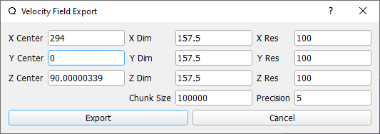
Fig. 145 The Velocity Field Dialog
The parameter Chunk Size is used to partition the evaluation points and only send a size defined by this parameter to the GPU, to prevent memory issues on certain GPU models.
Create Wind Fields
The main purpose to sample wind field is to record the waked inflow behind a wind turbine and use this data as a quick way to assess the influence of wake interaction in a simulation. The advantage is that the waked flow only has to be evaluated once and can then be used across any number of new simulations.
A wind field can be sampled” from a simulation. The wind field size is defined by the parameters in the *Create Wind Field Dialog (see Fig. 146), which is accessed by pressing the create Wind Field button in the Cut Plane Dialog. The plane in which the wind field is sampled is always oriented normal to the global x-direction. In the dialog the user can specify the field dimensions, its location and resolution. Furthermore, analogue to the cut-plane definition, the user can choose from which timestep the wind field should be sampled, and also apply a modulus to skip steps.
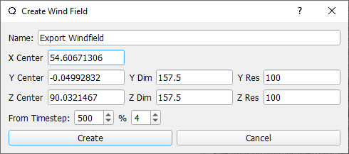
Fig. 146 The Create Wind Field Dialog
After a wind field has been generated from a simulation it appears in the object list of the wind field module and can be used in any simulation (see Fig. 147).
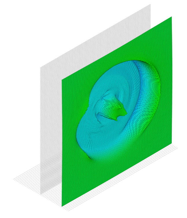
Fig. 147 A sampled wind field showing the wake deficit behind the rotor of a wind turbine
Cut-Plane Definitions
It is also possible to export a cut-plane definition (see Fig. 148) to automate the cut-plane generation of a simulation, or to generate a cut-plane definition to be used for multiple simulations. A cut-plane definition can be either exported from the top menu (see Fig. 148, left) or from the cut-plane definition dialog itself (see Fig. 148, right).
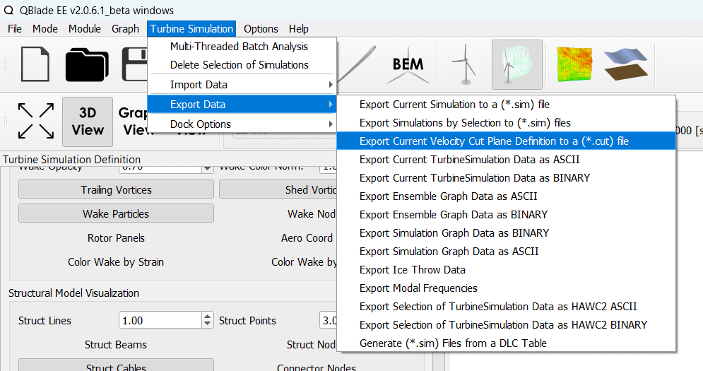
Fig. 148 The cut-plane definition (.cut) export option.
An exemplary cut-plane definition file is shown below. The parameters in the cut-plane definition are analogue to the parameters in the cut-plane dialog.
---------------------------------QBlade Cut Plane Definition File-------------------------------------
Generated with : QBlade CE v2.0.7-release_candidate_beta windows
Archive Format: 310023
Time : 15:49:33
Date : 08.05.2024

----------------------------------------------Plane Description---------------------------------------
exportPlane                             NAME
-5.000                                  XPOS
0.000                                   YPOS
90.000                                  ZPOS

0.000                                   XROT
0.000                                   YROT
0.000                                   ZROT

157.500                                 LENGTH
157.500                                 WIDTH

250                                     XRES
250                                     YRES

20000                                   TIMESTEP

false                                   ALLSTEPS
1                                       MODULUS
Automated Evaluation of Cut-Planes
Multiple cut-plane definitions can be predefined in the definition of a simulation object (see Fig. 149), before the simulation is evaluated. In this way it is possible to already define all cut-planes of interest at the start of a simulation. This feature also allows to generate cut-planes on-the-fly during a simulation even when the Store Replay option is not active. This can reduce the memory consumption drastically, especially for long simulations with finely resolved wakes.

Fig. 149 Assigning cut-plane predefinitions to a simulation object