Validation and Examples of Hydroelasticity
In this page, examples of hydroelastic simulations and validations with multiple substructure geometries are presented.
OC4 Semisubmersible ME Hydroelastic Model
The OC4 Semisubmersible ME Model validated in Validation Tests for Morison Equation (ME) can also be modeled with fully elastic members. The elastic members, together with the full Morison equation (see Morison Equation) at each element allow us to have fully hydroelastic simulations within QB. The structural properties of the individual elements were taken from 1.
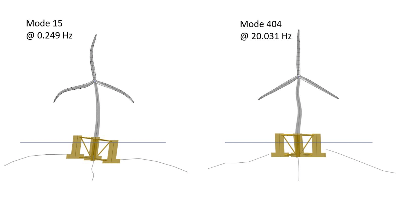
Fig. 167 Two exemplary modes of the flexible OC4 ME model.
Fig. 167 show two exemplary eigenmodes of the OC4 ME flexible model. Mode 15 on the left side has frequency 0.249 Hz and shows a combination of blade, tower and substructure deflections. For the substructure, it is mainly the cross-braces that are deflecting. Mode 404 on the right side of Fig. 167 has a frequency of 20.031 Hz. This mode shows a deflection of the three base and upper columns relative to each other. We note that there is also a tower deflection taking place in this mode. The high frequency of Mode 404 is also an argument for simulating the OC4 substructure as a rigid body if the local forces on the substructure are not required. The excitation frequencies from wind and waves are significantly lower than the eigenfrequencies of these modes. We also note that both modes shown in Fig. 167 also include the deflection of the mooring cables. All flexible members are taken into account when performing the eigenmode analysis within QB.
The flexible OC4 ME model was simulated in a regular sea state with \(H\) = 6 m and \(T\) = 10 s. No aerodynamic loads were applied on the turbine and the wave direction was chosen to coincide with the positive surge direction. The local loads for two locations were recorded: the lowest position of the main column and the connection point of the cross brace 1 with the upper column 1 (see Fig. 168).
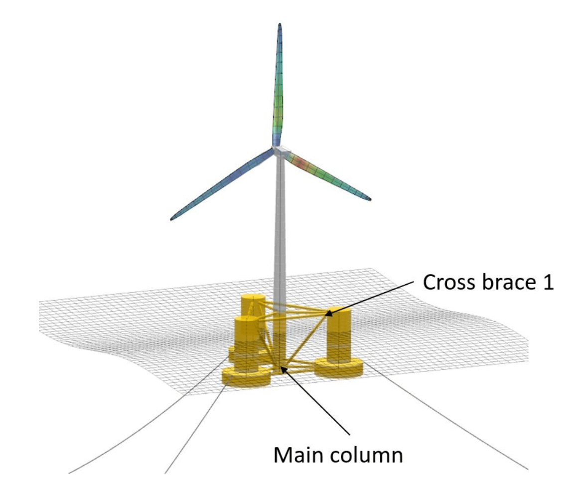
Fig. 168 Load sensor locations for flexible OC4 ME calculations.
Fig. 169 shows the local forces at the main column and the cross brace for the initial 400 s of the regular sea state simulation. We can see that the forces behave as expected. The source of the local forces at the main column bottom location arise mainly from the hydrodynamic and gravitational loads. The local force in the x-direction (surge) has an oscillatory behavior around 0 kNm, which can be explained by the oscillatory nature of the hydrodynamic wave loads in surge direction. This also explains the small forces in the y-direction (sway) since no wave loads are acting in this direction. Finally, in z-direction (heave), the oscillatory wave loads have a non-zero mean value. This comes from the gravitational loads acting in the z-direction. These localized loads can be used to design the individual components of a floating wind turbine substructure.
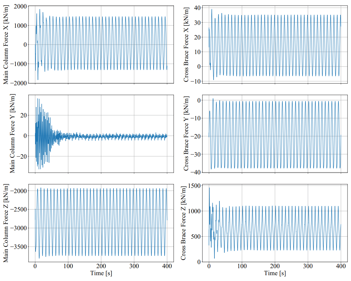
Fig. 169 Local forces at two locations of the OC4 ME flexible substructure.
Fig. 170 shows the corresponding local deflections of the main column and cross brace. We can see in this figure that the substructure deflections at these positions are very small, not even reaching 1 mm. This comes from the large stiff structures that make up the OC4 substructure. Fig. 170 shows that the rigid substructure assumption made for this model is a valid.
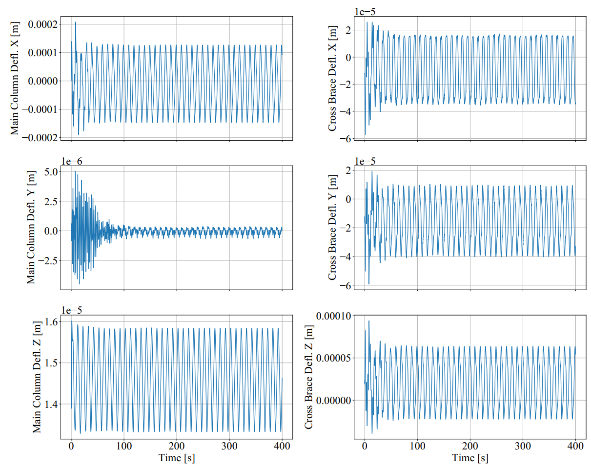
Fig. 170 Local deflections at two locations of the OC4 ME flexible substructure.
10 MW TetraSpar Hydroelastic Model
In Fig. 171, we show a hydroelastic model of a 10 MW turbine mounted on an up-scaled TetraSpar substructure 2. The modelling of this substructure is particularly challenging because it features a flexible suspension between the upper floater structure and the lower keel. Within QB, this suspension system can be modelled as a cable element similar to the mooring system (Section XXX). The TetraSpar model shown in Fig. 171 is composed of flexible Morison elements and we are therefore capable of accurately calculating the local loading on each element even when the substructure model is highly deflected. An example of this is shown on the right hand side of Fig. 171. This extreme roll position is unlikely to happen in reality, but being able to simulate such conditions in QB is a good example of the modelling capabilities of the tool.
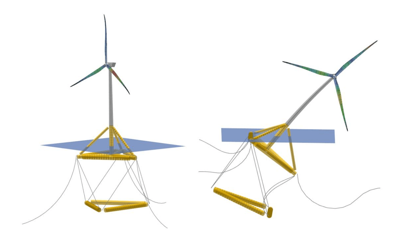
Fig. 171 Hydroelastic model of a 10MW turbine on an up-scaled TetraSpar substructure.
- 1
DTU. HAWC2 OC4 Semisubmersible model. https://www.hawc2.dk/models, 2021. [Online; accessed 2023-05-19].
- 2
Michael Borg, Morten Walkusch Jensen, Scott Urquhart, Morten Thøtt Andersen, Jonas Bjerg Thomsen, and Henrik Stiesdal. Technical definition of the tetraspar demonstrator floating wind turbine foundation. Energies, 2020. URL: https://www.mdpi.com/1996-1073/13/18/4911, doi:10.3390/en13184911.