BEM Analysis Overview

Fig. 84 The BEM module in QBlade’s main tool bar.
The Steady BEM Analysis tool allows the user to run aerodynamic simulations with very low computational expense, short run times and generally accurate preliminary results with regard to rotor performance parameters. The module is very useful for:
Performing a first evaluation of a blade design,
Calculating a fast estimate on annual energy production (AEP), or
Identifying control strategies through parameter studies.
This section gives insight into the three submodules Rotor BEM, Characteristic BEM and Turbine BEM.
Rotor BEM
In the Rotor BEM submodule, the user can carry out rotor blade simulations over a range of tip speed ratios (TSRs). A rotor simulation can only be defined when at least one rotor blade is present in the database (see Blade Design Overview). When defining a rotor simulation in the Analysis Settings box, the user can select the desired corrections to the BEM algorithm and the simulation parameters. Once a simulation is defined, the user can select a range of TSRs, and the incremental step for the simulation.
A rotor simulation is always carried out with dimensionless arguments. The freestream velocity is assumed to be uniform and the rotor radius is normalized for the computation. This implies that no dimensional power curve or load distributions (e.g. bending moment) can be computed during a rotor simulation.
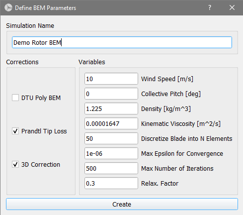
Fig. 85 Definition of a Rotor BEM simulation.
Characteristic BEM
In the Characteristic BEM submodule simulations can be carried out over a specified range of windspeeds, rotational speeds and pitch angles. By right-clicking on each graph in the graphics module, the user can specify the plotted variables which are displayed. When the selected windspeed, rotational speed or pitch angle is changed in the top toolbar, the series of curves is changed accordingly. This submodule is of great help when designing custom control strategies for variable rotational speed and/or pitch controlled wind turbine rotors.
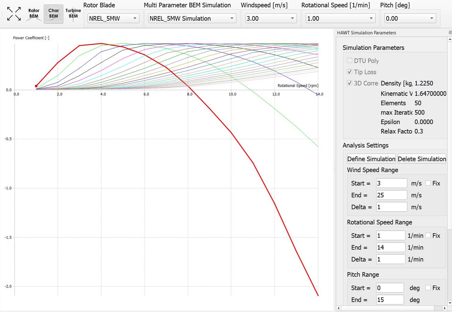
Fig. 86 Result of a characteristic BEM simulation. The \(C_p\) coefficient is plotted over \(rpm\), showing multiple wind speeds curves for a constant pitch angle.
Turbine BEM
In the Turbine BEM submodule, the user can simulate steady state BEM simulations. To define a wind turbine, a rotor blade must be present in the runtime database. In preparation for the simulations, a turbine has to be set up. This requires specification of the turbine type and turbine operational parameters. The turbine type is defined by:
Power Regulation:
None (stall): A stall regulated turbine has no pitch control and the power output is limited solely when stall occurs at the rotor. Designing a stall turbine that limits its power to the desired output and at the desired windspeed requires an iterative approach.
Pitch limited: Requires the user to specify a nominal power output. When the windspeed that yields the nominal power output is reached, the blades are pitched to reduce the power for higher windspeeds to the nominal output.
Prescribed: Allows to set the pitch to an arbitrary value defined in an
.txtfile. This option is useful to match a certain control behavior or for code-to-code comparisons.
Transmission:
Single: One stationary rotational speed in which the turbine operates over the whole range of windspeeds.
2-step: Two rotational speeds and a windspeed at which the transmission switches have to be selected.
Optimal: A minimum and a maximum value for the rotational speed has to be selected. Additionally, the user selects a desired TSR from which a rotational speed is computed for every given wind speed during the simulation.
Prescribed: Allows the user to set the rpm to an arbitrary value defined in an
.txtfile. This option is useful to match a certain control behavior or for code-to-code comparisons.
Further parameters that need to be selected by the user are shown in Fig. 87. At \(V_{cut in}\), the turbine starts and at \(V_{cut out}\) the turbine stops operation. To account for power losses that are not of aerodynamical nature but are caused by the efficiency of the generator and the gearbox, a value for fixed losses and a value for variable losses can be selected. The equation in which these losses are implemented is:
where, \(k_v\) is the variable loss factor and \(P_{fixed}\) the fixed losses. Finally, a previously defined turbine blade has to be selected.
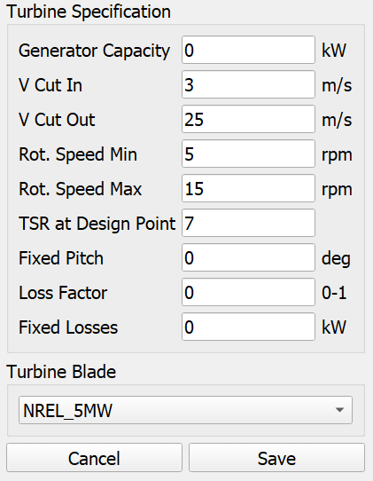
Fig. 87 Turbine specification dialogue.
After the turbine has been added to the runtime database, the BEM simulation can be executed identically to the Rotor BEM described above. The simulation is carried out over the specified range of windspeeds with the selected incremental step size.